MA - Fury
 |
Specification:
|
||||||||||||||||||||||||||||||||||||||||||||
| Documents: | |||||||||||||||||||||||||||||||||||||||||||||
 Manual 50/60 Expert |
 Manual Fury 55 |
 |
|||||||||||||||||||||||||||||||||||||||||||
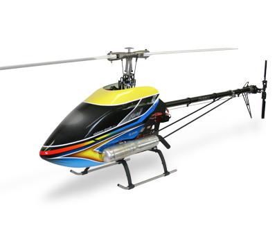
| All Popular 3-D Features Plus Improved Main And Tail Rotor Systems (Inc. Graphite Torque Tube And Pushrods), New Designed Swash- Plate And “Extreme Duty” Fuel System |
| Fully Ball Bearing Supported |
| Factory Pre-Set Gear Mesh Fully Supported For Extreme Duty |
| Engine Is A “Non-Stressed” Member Of The Drive System |
| Very Low Parts Count / Replacement Prices |
| Rigid C.N.C. Composite Frame Design |
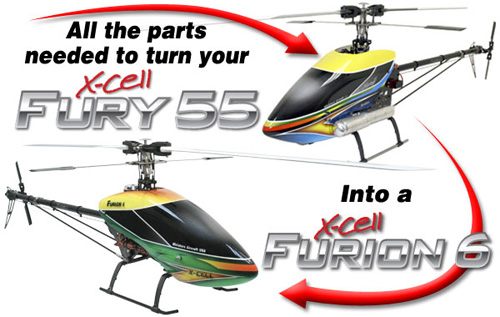
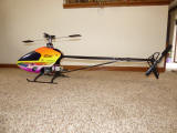
Miniature_Aircraft USA has just released a conversion kit that will allow you to convert a nitro powered Fury 55 into the latest electric powered X-Cell Furion 6. The part number is MA1029-2 and the kit is available from all Miniature_Aircraft stockists now.
Miniature_Aircraft has also released a flybarless (FBL) rotorhead conversion that will fit both the Fury 55 and Furion 6.
| Late 2001 updates: |
Logo on rear of frame - The "XL" cutout was added. Auto rotation Hub update - The early gold auto rotation hubs had a problem where the bearing sleeve would slip inside the hub. This was resolved by grinding flats on the sleeve and inserting set screws in the hub. |
| Early 2002 updates: |
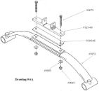
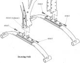
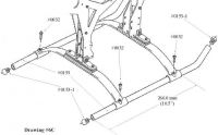
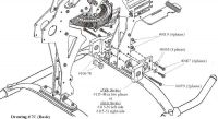
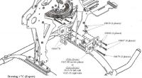
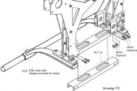
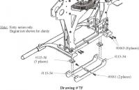
Two changes were made to stiffen the frame assembly. According to X-Cell "These two changes have SIGNIFICANTLY enhanced the rigid nature of the frame, …" Motor mount spacers - The two spacers were replaced with the block #115-53. Bottom frame rails - The bottom frame rails and spacers were replaced with the g10 bottom plate #115-57. |
| Late 2002 updates: |
Swash plate update - The original swash plate did not have the cutouts for getting to the inner links. The updated titanium swash plate with the cutouts was added. Clutch driver update - The bearing block was changed to a threaded block (versus through holes) to prevent bearing preload. The Driver bearing sleeve was updated from aluminum to steel. The new bearing block can be identified by having threaded mounting holes. I believe the new driver units can be identified by the set screws in the clutch driver. |
| Early 2003 updates: |
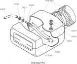
Clutch Bell - Updated to black color. Frame logo - The "XL" cutout was changed to "Fury". Parts coloring - All gold and black replaced with titanium color. Tank Fitting - The original tank had a straight fitting feeding the engine. This required the bubble in the side of the canopy. In 2002 the angle fitting was released but as an option. Sometime in 2003 it became standard in the kits. |
| Mid 2003 updates: |
Frame logo - The "XL" cutout was changed to "Fury". |


Fine Tuning Swashplate Linkages
This procedure will ensure that no cyclic control interaction occurs during collective changes.
Initial Setup
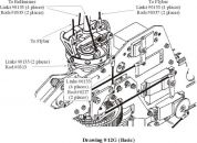
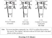
Assemble swashplate control system using rod lengths found in the instruction manuals Set swashplate type and servo direction as per instructions, to ensure correct swashplate movement when collective/cyclic pitch is applied Set all trims to zero Set all sub-trims to zero Turn off any cyclic mixes Set 50% point of pitch curve at 50% (center stick equals all swashplate servos centered)
Servo Wheel Setup
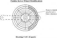
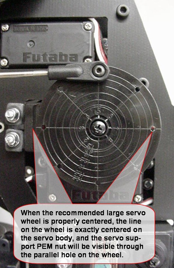
The most important starting point for setting up the swashplate linkages, is to make sure that the servo wheels are exactly centered on the servos.
This will require trial fitting each servo wheel/arm at various positions until the center is found OR simply drill your own centered hole at the proper distance stated in the instructions, and mount the ball.
This picture shows a Futaba servo installation, using the extra-large servo wheel. This wheel has alignment lines scored on it, which can be used to aid in alignment.
![]()
Swashplate Control Links
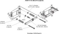
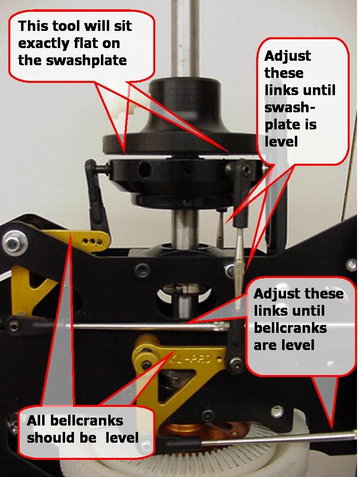
With the collective pitch still set at 50%, and the servo wheels now centered, fine adjust the length of the links between the three cyclic/collective servos and the bellcranks so that the bellcranks are exactly level to the frame (use a small level if its available)
Swashplate alignment will be made much easier by using the swashplate alignment tool #0513 (shown in these pictures), however a small level can be used.
Slide the alignment tool over the mainshaft and down onto the swashplate. Fine adjust the two links that connect the bellcranks to the front swashplate balls, until the swashplate is exactly level. The tool will rest flat when the swashplate is level, or as in the picture, the gap between the tool and the swashplate will be equal on all sides.
Note: the Fury model used in these photos includes optional CNC Aluminum Bellcranks and Reverse Threaded Control Rods, which can be purchased separately but are not standard in the kit. Use of these components is not required to apply the setup procedure represented.
![]()
Eliminate Any Control Interaction
With the linkages all now fine tuned for center pitch, move the collective pitch to full high pitch and check for level swashplate. Do the same thing at full low pitch.
If the swashplate is perfectly level, then no further setup is required at this point. If the swashplate is NOT level at full collective throws, this is easy to correct if you want, using your transmitter.
Using the programmable mix feature of your radio, setup a linear mixer to correct this.
If the swashplate is not level front and back, mix collective to elevator
If the swashplate is not level left and right, mix collective to aileron
For each mix, adjust the left/right/up/down values at full high and full low pitch so that the swashplate is exactly level. Using the alignment tool, this is easy to determine, since it will sit exactly flat on the swashplate. Typically, if the servo wheels have all been installed centered, this mix will be a very small percentage (less than +/-5%)
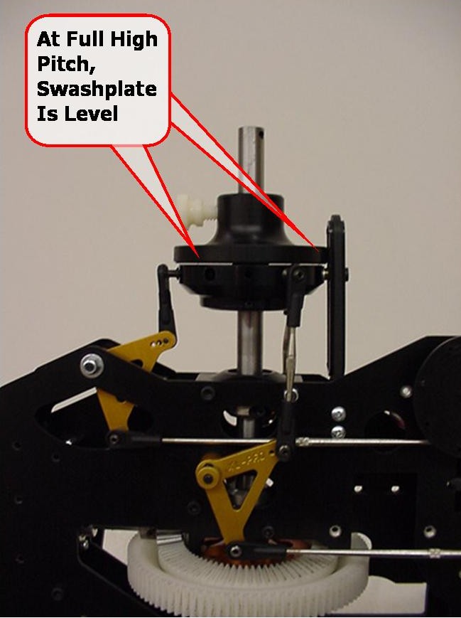
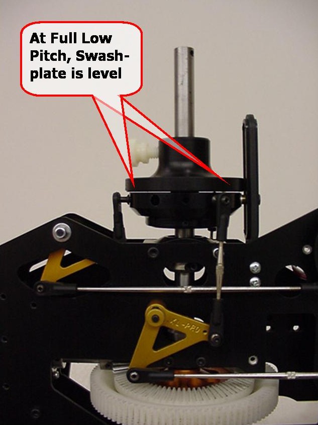
Once this is complete, return to center stick to confirm that the swashplate is still level.
Make sure that whatever mixer values are applied, are also applied to each flight mode that you have setup.
At this point, all mechanical linkages to the swashplate are correct. Install the rotor head and follow the recommended (or your normal) pitch settings by adjusting the pitch curve settings in the radio. Do not adjust any of the linkages set in this procedure once it is complete.
Fine Tuning Constant Drive Assembly
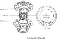
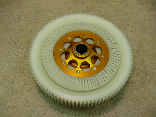
This instruction manuals cover basic assembly of the constant drive assembly. The purpose of this procedure is to address some of the questions we've gotten from customers
Initial Setup
The constant drive assembly has been designed with very close tolerances to ensure a long service life. When initially assembled, the unit may seem somewhat stiff in operation.
Install and operate the helicopter for a few tanks of fuel and then recheck unit operation. It should now be very smooth and turn freely.
This procedure will focus on a couple areas of the unit to pay attention to
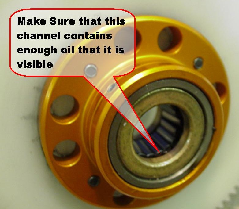
Prior to assembly of the unit, make sure the sprag bearing is well oiled.
The bearing manufacturer recommends using Automatic Transmission Fluid as the lubricant, however extensive testing has shown that the use of Tri-Flow oil to be equally as appropriate.
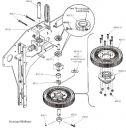
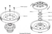
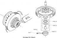
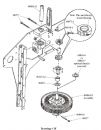
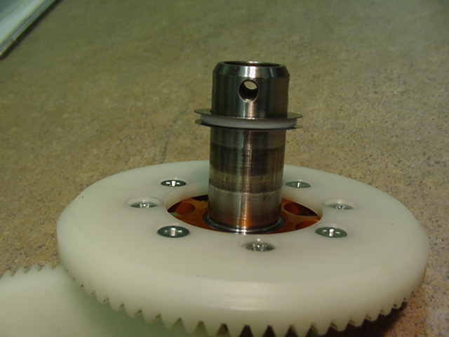
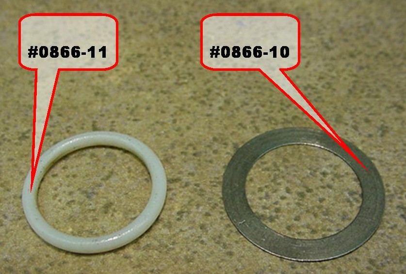
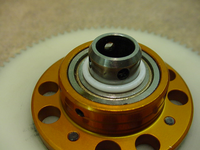
This shows the correct assembly order for the #0866-10 spacer shims and the #0866-11 teflon o-ring that slide over the center axle, and fit between the t/r drive and the auto hub
Fine Adjustment of Constant Drive Fit
If after a few gallons of fuel have been flown, the constant drive unit is still somewhat stiff to operate, it is possible to loosen the fit by lightly sanding the lower #0866-11 teflon o-ring. Do not make any changes to the upper teflon o-ring or its spacers, as this will affect the gear mesh for the front t/r transmission.
Under normal circumstances, it is more likely that a small amount of vertical play will have appeared between the main gear and the t/r drive gear. This can be demonstrated by grabbing the outer edges of the main gear and moving it vertically. This is normal and desirable to ensure that the unit operates smoothly. If over time, this play becomes excessive, insert an additional #0866-10 shim under the bottom teflon o-ring against the auto-hub.. This will slightly tighten the unit.
Optional Features for Fury 50 Basic
| part number | description | details |
| 0232 | High Speed Tail Drive Front Gear | Replaces #0231 16tooth bevel gear |
| 0533 | Easy Off Flybar Weights | Do not require flybar paddle removal |
| 0536 | Adjustable Roll Bellcranks | 2 bellcranks - Fury requires additional bellcrank - order 1-#0536-1,2-#106-02,1-#0101 |
| 0537 | Pro Wash-Out Mixer Arm Kit | |
| 0538 | Pro Adjustable Bell Mixers | Five mixing ratios |
| 0540 | Main Shaft Thrust Bearing Kit | |
| 0547 | Speed Up T/R Gears | Requires Use of lightweight T/R blades |
| 0551 | Slipper - Adjustable Drag T/R Drive | For non-stepped mainshaft |
| 0561 | Pro Adjustable CG Paddles | 15-30gm variable weight using brass inserts |
| 0561-5 | Pro-2 FAI Paddles | variable 24-45gm. CG corrected |
| 0571 | Machined Washout Hub | |
| 0579-4 | CNC Machined Aluminum Fan | |
| 0597 | Machined Bearing Spacer kit for Plastic Bellcranks | |
| 0818 | Rudder Graphite Rear Servo Mount | |
| 0823 | Machined Upper Thrust Bearing Block with Anti-Rotation | |
| 0844 | Aluminum Head Block | Included in #0848 |
| 0846 | Stainless Steel Head Axle | |
| 0848 | Pro CNC All Metal Rotorhead | |
| 0850 | CNC Angled Flybar Control Arm Kit | |
| 0859 | Machined Pro T/R Bellcrank and Pitch Slider | Requires #0422 or #0861 T/R Housing |
| 0860 | Aluminum T/R Grips | |
| 0861 | Machined Aluminum T/R Gear Box Housing | |
| 0866 | Split Gear Constant Drive | (Order #0866 - 9:1, #0866-1 - 9.3:1, #0866-2 - 9.5:1) |
| 0883 | Linear Servo Link Kit | (Order #0883 for JR and #0883-1 for Futaba Servos) |
Optional Features for Fury 50 Expert
| part number | description | details |
| 0232 | High Speed Tail Drive Front Gear | Replaces #0231 16tooth bevel gear |
| 0533 | Easy Off Flybar Weights | Do not require flybar paddle removal |
| 0536 | Adjustable Roll Bellcranks | 2 bellcranks - Fury requires additional bellcrank - order 1-#0536-1,2-#106-02,1-#0101 |
| 0537 | Pro Wash-Out Mixer Arm Kit | |
| 0538 | Pro Adjustable Bell Mixers | Five mixing ratios |
| 0540 | Main Shaft Thrust Bearing Kit | |
| 0547 | Speed Up T/R Gears | Requires Use of lightweight T/R blades |
| 0561 | Pro Adjustable CG Paddles | 15-30gm variable weight using brass inserts |
| 0561-5 | Pro-2 FAI Paddles | variable 24-45gm. CG corrected |
| 0579-4 | CNC Machined Aluminum Fan | |
| 0597 | Machined Bearing Spacer kit for Plastic Bellcranks | |
| 0818 | Rudder Graphite Rear Servo Mount | |
| 0823 | Machined Upper Thrust Bearing Block with Anti-Rotation | |
| 0846 | Stainless Steel Head Axle | |
| 0848 | Pro CNC All Metal Rotorhead | |
| 0850 | CNC Angled Flybar Control Arm Kit | |
| 0859 | Machined Pro T/R Bellcrank and Pitch Slider | Requires #0422 or #0861 T/R Housing |
| 0860 | Aluminum T/R Grips | |
| 0861 | Machined Aluminum T/R Gear Box Housing | |
| 0883 | Linear Servo Link Kit | (Order #0883 for JR and #0883-1 for Futaba Servos) |
Optional Features for Fury 60 Basic
| part number | description | details |
| 0232 | High Speed Tail Drive Front Gear | Replaces #0231 16tooth bevel gear |
| 0533 | Easy Off Flybar Weights | Do not require flybar paddle removal |
| 0536 | Adjustable Roll Bellcranks | 2 bellcranks - Fury requires additional bellcrank - order 1-#0536-1,2-#106-02,1-#0101 |
| 0537 | Pro Wash-Out Mixer Arm Kit | |
| 0538 | Pro Adjustable Bell Mixers | Five mixing ratios |
| 0540 | Main Shaft Thrust Bearing Kit | |
| 0547 | Speed Up T/R Gears | Requires Use of lightweight T/R blades |
| 0551 | Slipper - Adjustable Drag T/R Drive | For non-stepped mainshaft |
| 0561 | Pro Adjustable CG Paddles | 15-30gm variable weight using brass inserts |
| 0561-5 | Pro-2 FAI Paddles | variable 24-45gm. CG corrected |
| 0571 | Machined Washout Hub | |
| 0579-4 | CNC Machined Aluminum Fan | |
| 0597 | Machined Bearing Spacer kit for Plastic Bellcranks | |
| 0818 | Rudder Graphite Rear Servo Mount | |
| 0823 | Machined Upper Thrust Bearing Block with Anti-Rotation | |
| 0844 | Aluminum Head Block | Included in #0848 |
| 0846 | Stainless Steel Head Axle | |
| 0848 | Pro CNC All Metal Rotorhead | |
| 0850 | CNC Angled Flybar Control Arm Kit | |
| 0859 | Machined Pro T/R Bellcrank and Pitch Slider | Requires #0422 or #0861 T/R Housing |
| 0860 | Aluminum T/R Grips | |
| 0861 | Machined Aluminum T/R Gear Box Housing | |
| 0866 | Split Gear Constant Drive | (Order #0866 - 9:1, #0866-1 - 9.3:1, #0866-2 - 9.5:1) |
| 0883 | Linear Servo Link Kit | (Order #0883 for JR and #0883-1 for Futaba Servos) |
Optional Features for Fury 60 Expert
| part number | description | details |
| 0232 | High Speed Tail Drive Front Gear | Replaces #0231 16tooth bevel gear |
| 0533 | Easy Off Flybar Weights | Do not require flybar paddle removal |
| 0536 | Adjustable Roll Bellcranks | 2 bellcranks - Fury requires additional bellcrank - order 1-#0536-1,2-#106-02,1-#0101 |
| 0537 | Pro Wash-Out Mixer Arm Kit | |
| 0538 | Pro Adjustable Bell Mixers | Five mixing ratios |
| 0540 | Main Shaft Thrust Bearing Kit | |
| 0547 | Speed Up T/R Gears | Requires Use of lightweight T/R blades |
| 0561 | Pro Adjustable CG Paddles | 15-30gm variable weight using brass inserts |
| 0561-5 | Pro-2 FAI Paddles | variable 24-45gm. CG corrected |
| 0579-4 | CNC Machined Aluminum Fan | |
| 0597 | Machined Bearing Spacer kit for Plastic Bellcranks | |
| 0818 | Rudder Graphite Rear Servo Mount | |
| 0823 | Machined Upper Thrust Bearing Block with Anti-Rotation | |
| 0846 | Stainless Steel Head Axle | |
| 0848 | Pro CNC All Metal Rotorhead | |
| 0850 | CNC Angled Flybar Control Arm Kit | |
| 0859 | Machined Pro T/R Bellcrank and Pitch Slider | Requires #0422 or #0861 T/R Housing |
| 0860 | Aluminum T/R Grips | |
| 0861 | Machined Aluminum T/R Gear Box Housing | |
| 0883 | Linear Servo Link Kit | (Order #0883 for JR and #0883-1 for Futaba Servos) |

