Rotair
Rotair Tyke
An MFA clone developed in 1989 by Tim Angel with the resulting improvements in flying ability over the original.
Advert 1989 |
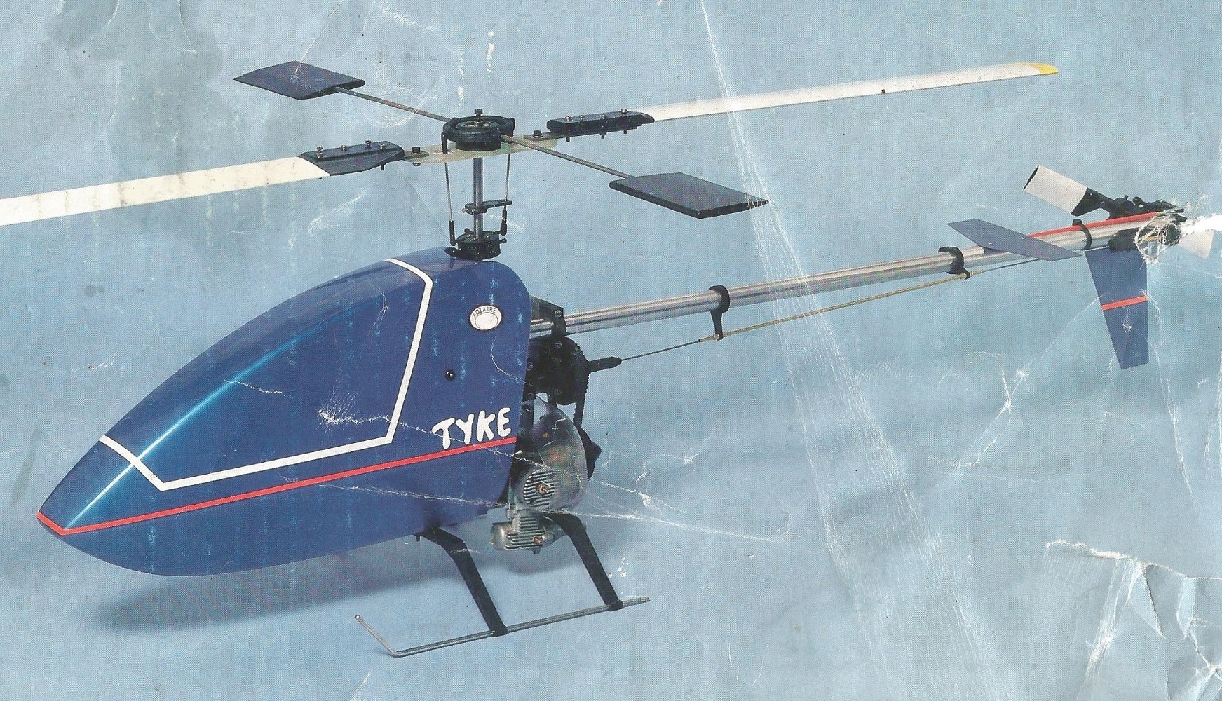
Box cover |


Historic comment is that it wasn't any good however like MFA Sport 500 in the hands of tyro's learning on their own then any problem would be the helicopters fault and not the pilots?? Note the comments by MB the reviewer; if built properly then it was a good learner that would loop which means it must have been some good...
Build Drawings - 1989
Build Instructions - Including basic flying tips and list of parts plus 1989 prices.
Tyke build review - 1989 by Editor MB including flying notes - Courtesy Model Helicopter World - www.modelheliworld.com
This is the refurbishing documentation with courtesy of Dave Jones (orig. from rcgroups.com)
Rotaire Tyke was a little known English fixed-pitch r/c heli designed by Tim Angel and was produced in England in the late 1980's.
There is a small bit of information about the Tyke here including a review in Model Helicopter World:
This was listed on Ebay and, in a moment of probable foolishnes, I spent some of my hard-earned on it.
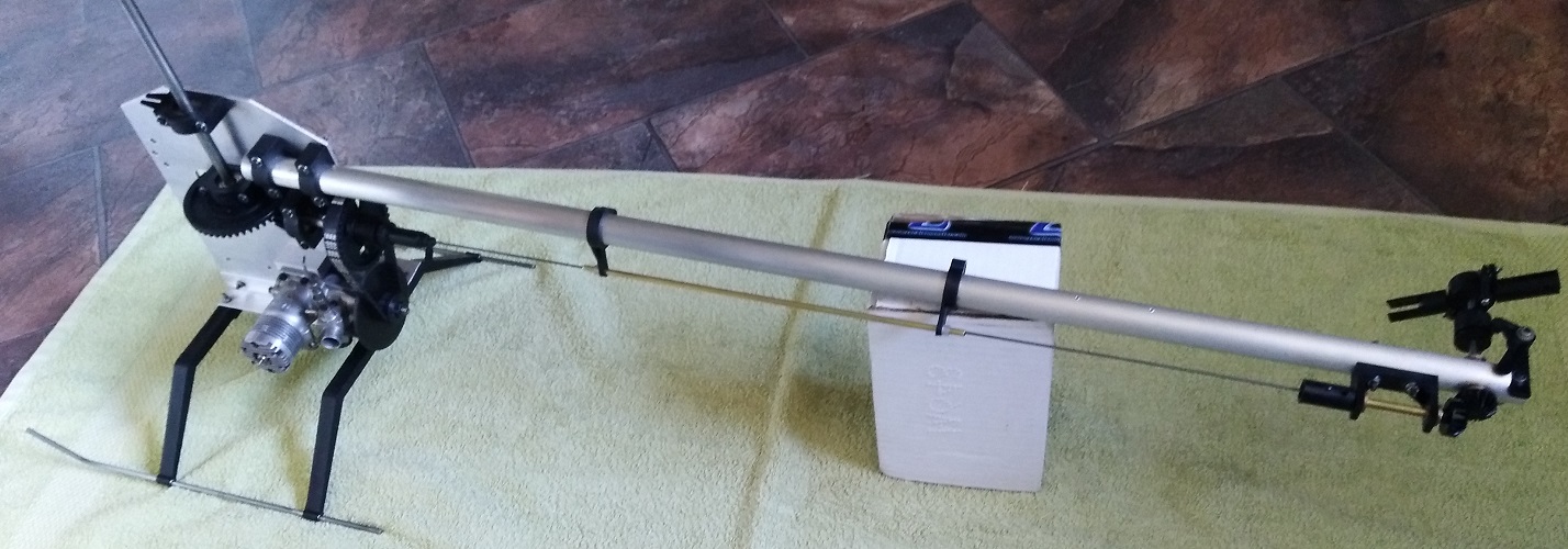
A couple of pics below. One showing what it should look like - scanned from the manual cover and the other pic showing what turned up (photo from Ebay) 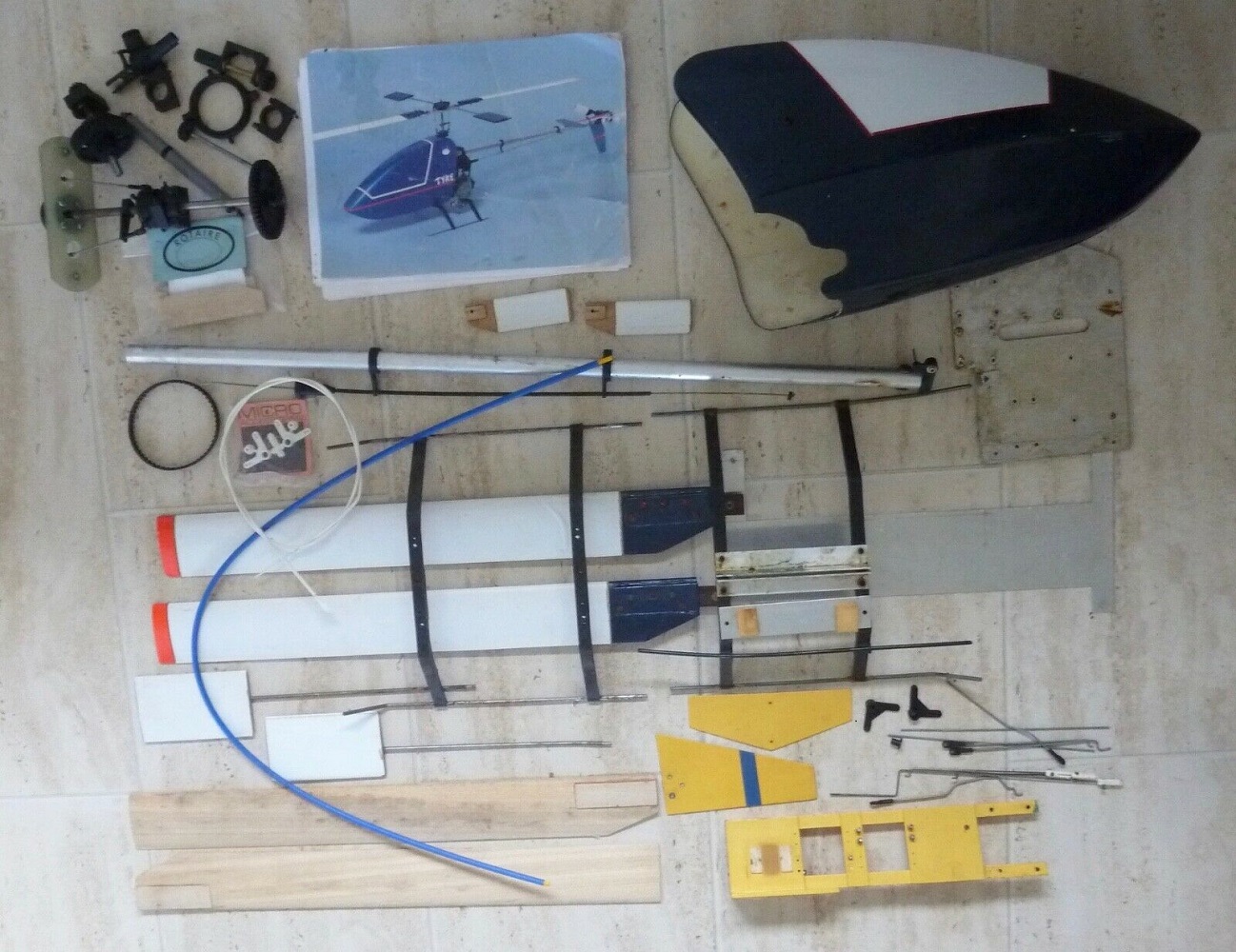
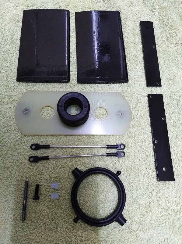
After a few weeks wait, a delivery van turned up and dropped off a scruffy looking parcel which turned out to contain a bunch of really dirty Tyke parts.
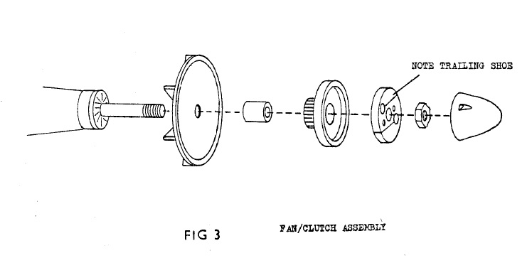
Looks like all parts are there which are needed to complete the heli except for the parts that would have been attached to the engine. So I'm missing engine mounts, fan, clutch bell with belt drive pulley, clutch and starter cone.
If I can't find these parts (likely) I will have to machine and fabricate my own. This should be fun as I have no originals to measure and no real idea of what they actually look like, apart from some sketches in the manual.
So, if anybody knows where there is one of these or knows of someone that has one and could measure some bits for me, I would be extremely grateful if you could let me know.
For the rebuild, I intend to follow the steps in the manual and clean repair/fabricate parts as they are called for.
So, step 1 - Undercarriage assembly:
Chose the better of the two sets of legs. These needed the openings for the skids to be bushed as they had been drilled oversize and the skids had been held in place with epoxy adhesive. Cleaned everything, machined aluminium bushes for the skid openings and glued them into the legs with CA.
Cleaned and straightened the music-wire skids and glued these into the above bushes with blue Loctite.
Cleaned and tidied up the aluminium chassis parts and bolted it all together using the original (cleaned up) bolts with new nuts and washers. 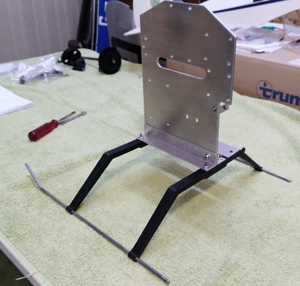
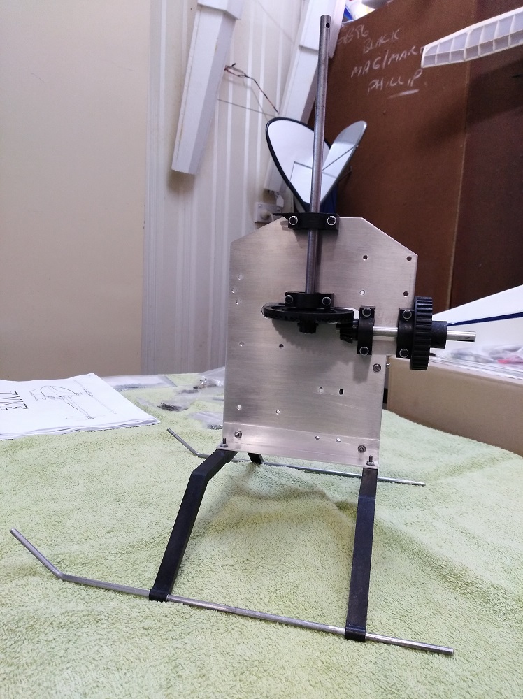
Main Gear and Pinion Shaft:
Cleaned both shafts of light surface rust and checked for straightness. Main shaft had a very slight bow which was probably there from new so I straightened that. Replaced all four bearings with quality 608zz bearings. Cleaned up some dings and a couple of rub marks on the gears. At some stage, one of the pinion shaft bearing blocks had been mounted back to front and had rubbed and slightly melted the pinion gear boss so tidied that up.
Bolted it together. Main gear is slightly warped and there is a bit of a tight spot in the mesh. Can't do too much about this - hopefuly the tight spot will loosen up with some running.
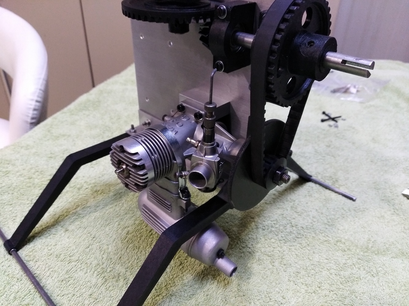
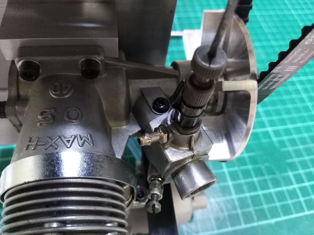
Next, I'll machine some aluminium engine mounts to suit the engine I'll be using. An OS Max-H 40 but with a dual needle carb from an OS FSR 40. Both the engine (NIB) and carb were gifts from fellow club members. Thanks chaps.
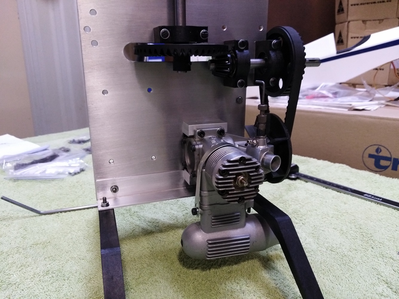
Engine Mounting:
Machined a pair of aluminium engine mounts to a size that allows the crankcase to just clear the chassis plate and also gives the 76mm centre to centre measurement between pinion shaft and engine crankshaft that the manual calls for.
There are currently no bolts in the lower mount as I will probably have to elongate the existing chassis holes so I can fit everything onto the engine crankshaft and have the pulleys lined up correctly. Drawing from the assembly manual below.
Needed an OS muffler mount extension to allow the muffler to clear the landing gear. I shortened the extension by 5mm to give 20mm of ground clearance.
The original belt and main pulley on the pinion shaft are XL type timing parts.
I 3D printed a couple of different sized XL pulleys to try and, using the original belt, was able to determine that the engine crank pulley should be 13 teeth.
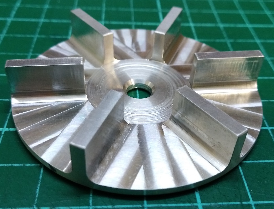
Also drew and 3D printed a fan to determine blade size and fan diameter etc.
All 3D printed parts will be replaced with machined aluminium once I have all the measurements sorted.
Just realised that I will also have to sort out a fan shroud.
I will have to skip the manual's 'Clutch and fan assembly' and 'Fan shroud' steps while I wait for some materials and parts to show up.
I did receive a new belt. It's a very common size (110 XL 031) and readily available although I did spend a couple of extra dollars for a quality one.
Tail Gearbox Assembly:
The tail uses four bronze bushes instead of bearings. Two are epoxied into the tail boom and two are pressed into the gearbox frame/bracket. The two in the tail boom have a small amount of wear and the others are good. Checked both shafts and had to straighten the tail rotor shaft as best I could. Both shafts have the plastic bevel gears moulded onto them and so are not really easily replaced. Both gears are good except one is very slightly warped but the gear mesh is still quite smooth.
The blade holders rotate on two 4BA bolts instead of a shaft. The plastic blade holders each have a 4BA steel insert moulded into them and this acts as a bearing surface on the 4BA bolts. The thrust loads are taken by the threads rather than the bolt heads. Anyway, both these bolts were bent so I machined a couple of replacements. All other parts were cleaned and assembled.
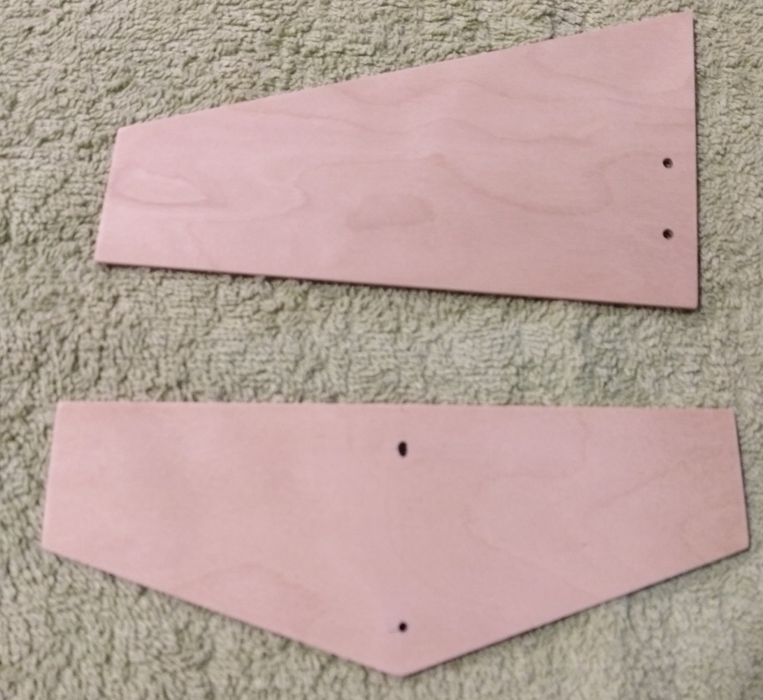
Cut out new fin and stab. from 1/16" ply to replace the warped and split originals. These are yet to be painted.
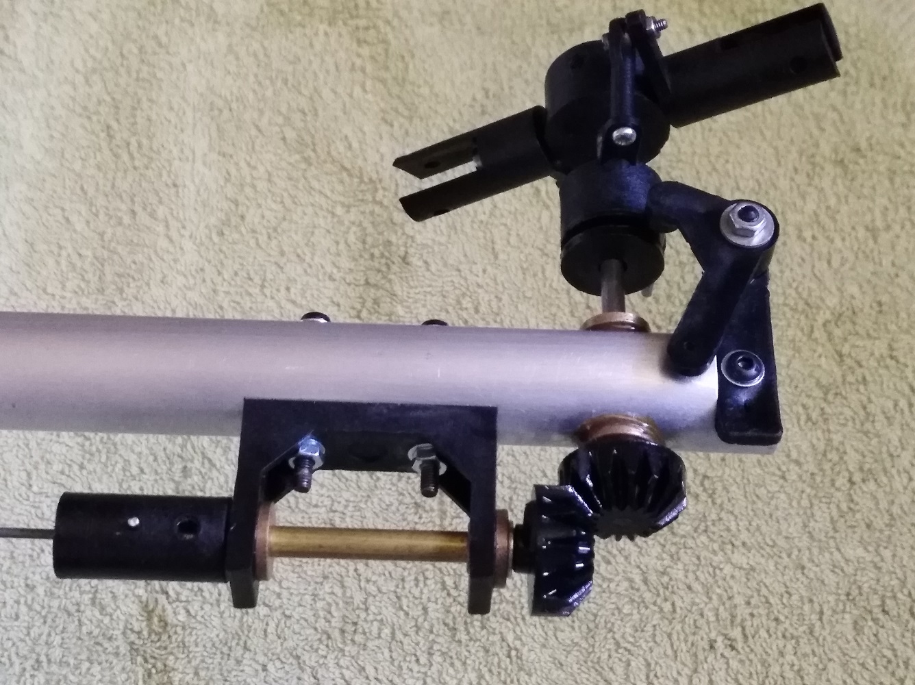
Boom and Tail Drive:
Cleaned all parts. Bent up a new 1/16" music wire drive and brass tail drive tube as these parts were in very poor condition. Machined one small part that centres the drive wire in the tail coupling - I'm sure I had the original but cannot find it!
Mounted the boom and tail drive parts with no issues.
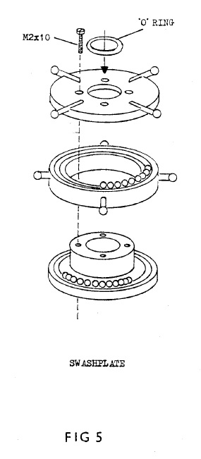
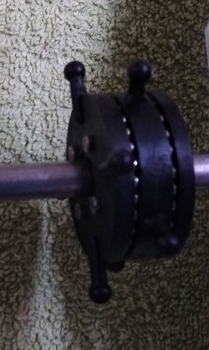
Swashplate:
This had a tight spot in part of it's rotation. Stripped and cleaned all the parts including the 58 steel balls. Checked the plastic link balls with the original ball-links and they are still a good fit. After re-assembly and oiling there was still the same tight spot. I tried 4 different ways of ligning up the parts but no difference. I then discovered that one of the four screw holes was mis-aligned. Sorted that out and now the swash is as smooth as silk. It was probably always tight in that spot from new.
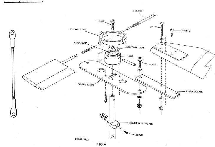
Rotor Head:
Stripped and cleaned all the parts. Repaired and Re-covered the flybar paddles with black Profilm.
The flybars are too badly corroded to be used and I'm waiting for materials to arrive to make some new ones.
Main Rotor Blades:
De-rusted and painted the steel Main Blade Holders with enamel and baked in Mrs Jones' oven.
Stripped the covering from the blades and fixed a couple of minor splits with CA and also epoxied new upper plywood root parts.
Now waiting to be covered with white Profilm and repainting the roots with black epoxy paint.
Rotor Head:
Had some free time this afternoon so made up a pair of flybars.
Assembled the head and mounted it to the main shaft.
The paddles are a bit of a loose fit on the flybars - there was a lot of epoxy in the flybar holes. So I may also have to resort to some epoxy to keep the paddles aligned.
Also got the canopy mount cleaned up and mounted to the chassis.

Blades - Main and Tail:
Got all the blades stripped, cleaned up and repaired. Painted the roots and tips. I need to get some covering this week to finish them, although I have toyed with the idea of clear coating them for that 'woodie' look.
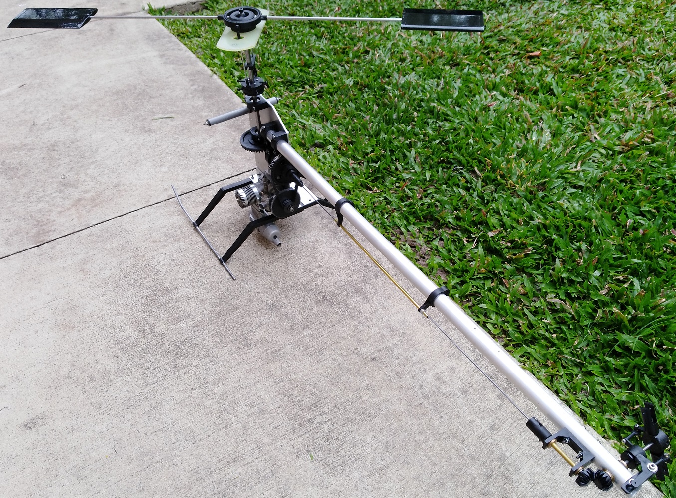
It's at the stage where I couldn't resist the opportunity for a mock-up. Still not sure what colour it will be when completed - probably yellow.
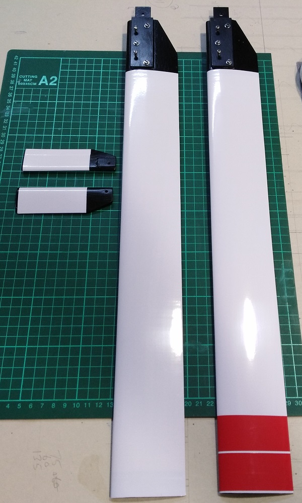
Blades - Main and Tail:
Finished covering the blades.
I ended up using HTVRont self adhesive vinyl and covered them as they would have done back in the day.
Vinyl I used: https://www.htvront.com/products/per...-cameo-cutters (also available on Ebay).
I did the covering job as per the great old-school covering how-to video below.
They came out pretty perfect. Even if I do say so myself.
All balanced and CG corrected - ready to mount.
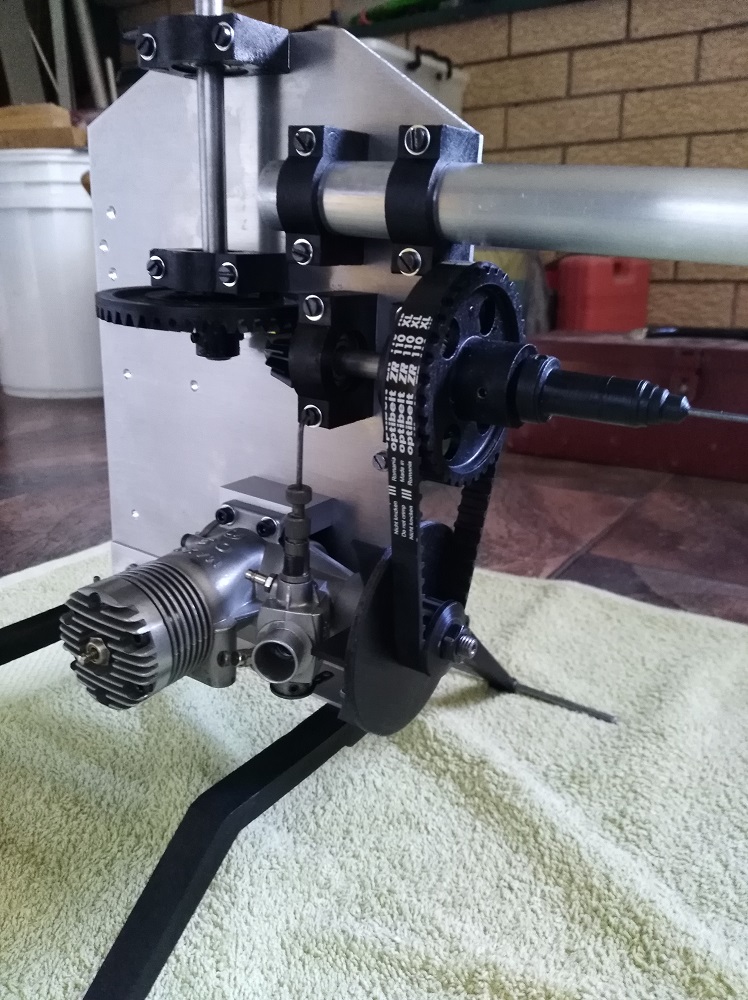
Clutch and Fan Assembly:
Machined a fan from aluminium. I have no real idea of what size the original was or what it was made of. Hopefuly, what I've made will do the trick.
Next up will be to start making a fan shroud and some clutch parts.
I have been a little slow on here lately as I've been rebuilding a JR Venture 30. Successfuly test hovered this morning.
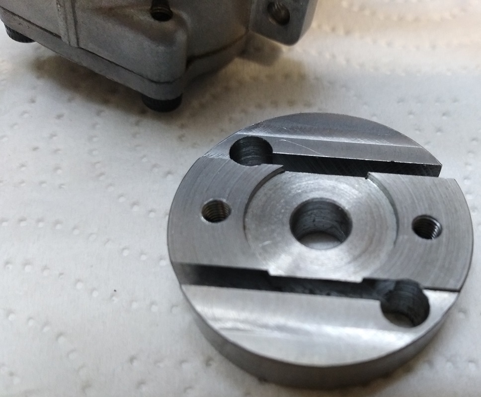
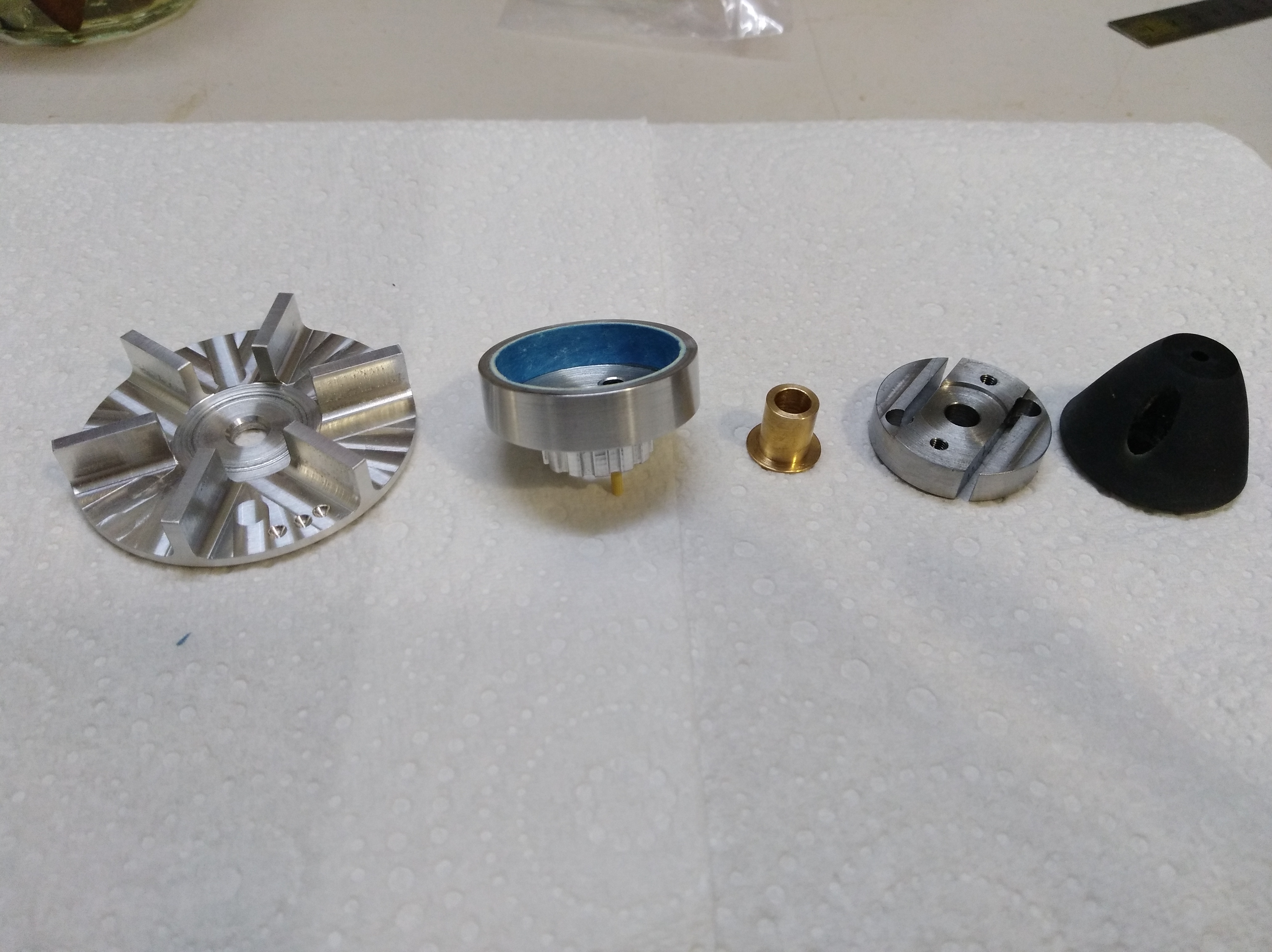
Machined up the steel clutch centre/shoes. All critical dimensions are the same as a GMP Cricket clutch so it should work ok as long as I get the gap between this part and the clutch liner right. The two threaded holes are for mounting the starter cone .
Balanced this part and also balanced the Fan.
Next up I'll make the clutch bell and attach the belt pulley to it (somehow).
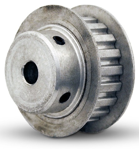
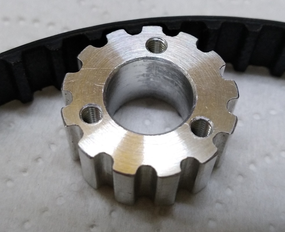
Started with a XL, 13 teeth, 1/2" wide, double flanged timing pulley similar to the first image below.
Machined off the flange swages and removed the steel flanges. Machined off the mounting boss and faced the pulley down to 9mm. Bored out the centre to 10mm diameter. Drilled and tapped three holes for mounting.
The pulley will fit onto the face of the (yet to be made) clutch bell, be aligned by a 10mm spigot and held in place by three M2.5 countersink head machine screws.
Finished making all the parts. Clutch liner is a Gaui NX4 liner that is cut down to size.
I'll try to make time this afternoon or tomorrow to put the engine on a test stand to test when the clutch engages and also to ensure there is enough mass in the parts so the engine has a good idle. If it will not hold a good idle, I will have to replace the 3D printed starter cone with a machined aluminium or steel one.
Next up will be the fan shroud/duct.
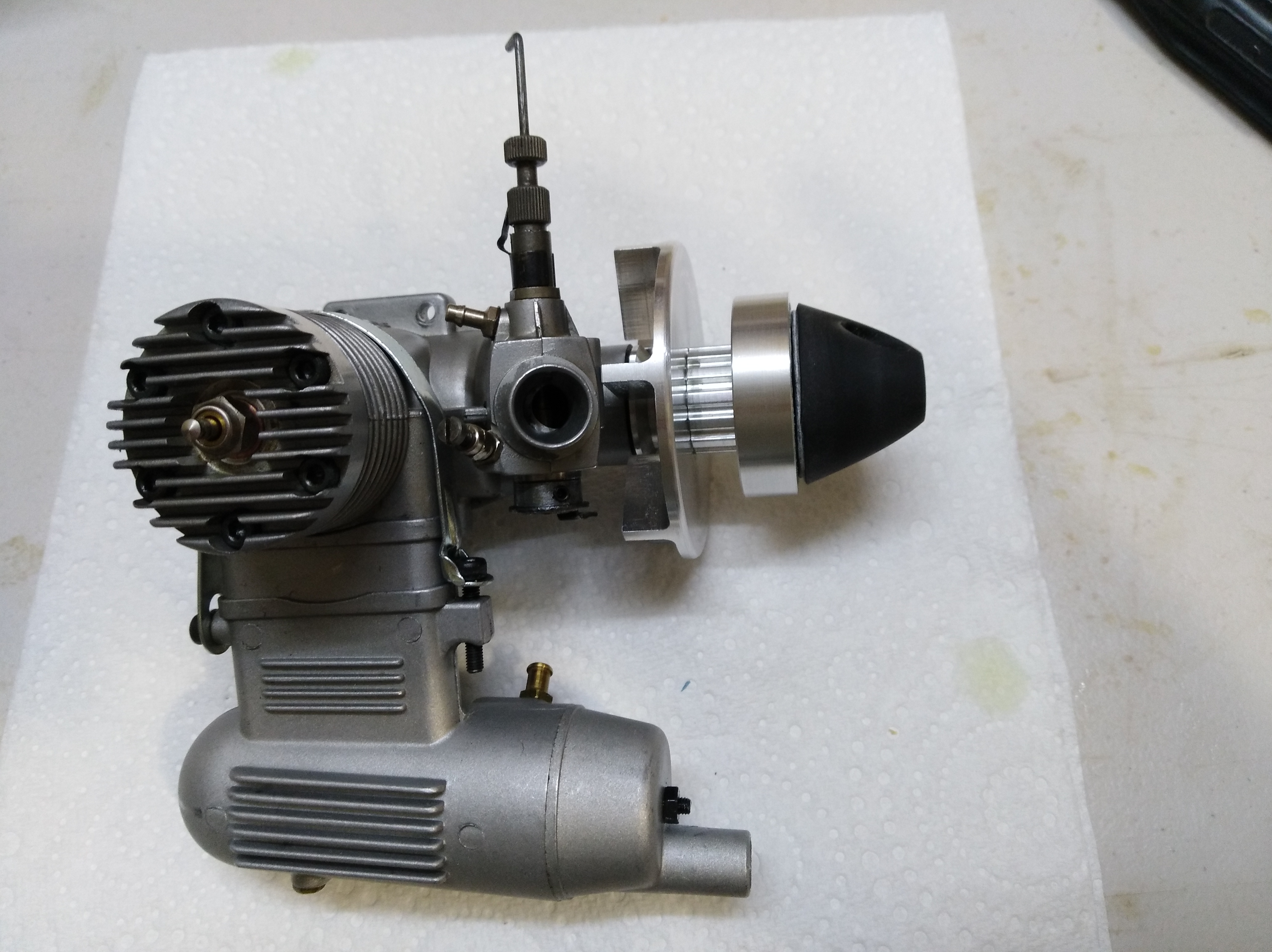
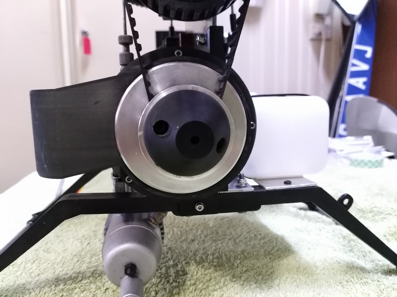
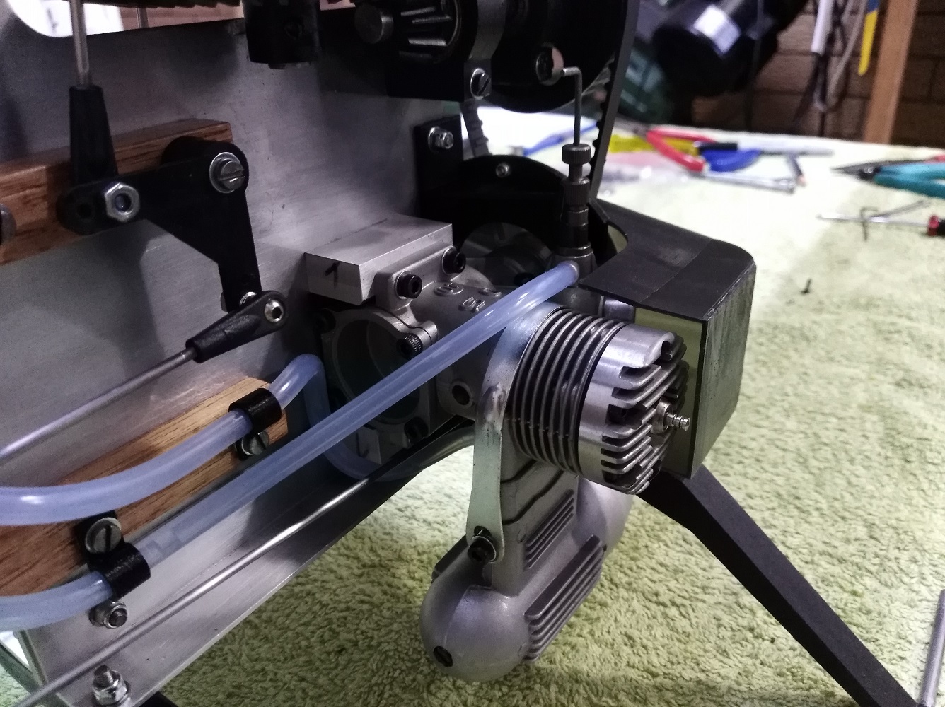
Put the engine on a test stand.
Engine idles fine and I can easily hold the Clutch Bell still between two fingers while the engine is idling.
I can no longer hold the clutch stationary once I get the engine to about 20% throttle.
So, I'm thinking test successful!
Back to the PC and drawing a fan shroud.

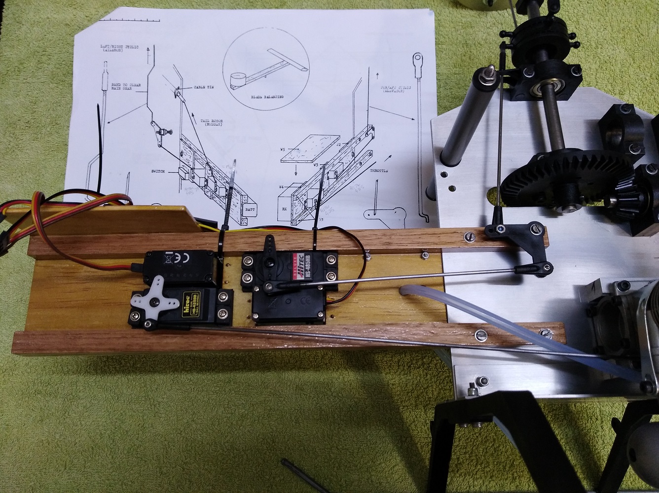
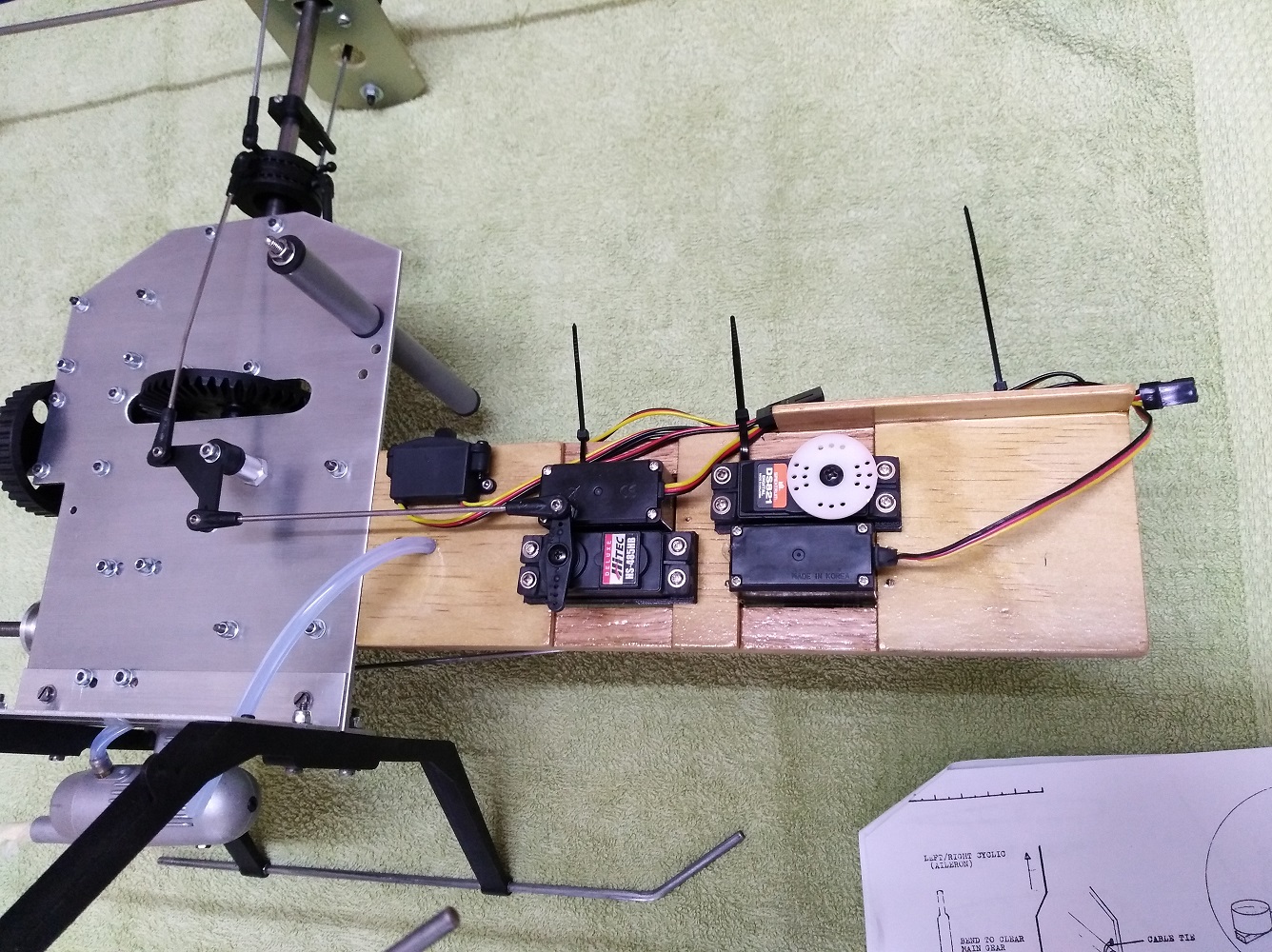
The original radio tray is in poor shape with many splits and cracks so I made a new one.
Got the servos installed and all the control runs except the tail rotor pitch, which I'll do once I've got the tail boom finally installed.
Traded the agricultural push rod Z-bends for threaded ball-links
It will be interesting to see how the throttle push rod stands up. It's 300mm (12") long, 2mm dia and unsupported. As per the manual.
Still working on the fan shroud/duct- getting there slowly.
Next will be fuel tank and plumbing.
Just bought three more oldish heli's. $60AUD each. Kalt Space Baron with radio and engine. Kyosho Concept 30 with engine. Hirobo Falcon 555 with engine.
They are being delivered by my daughter on Friday. Can't wait to see how bad they are!
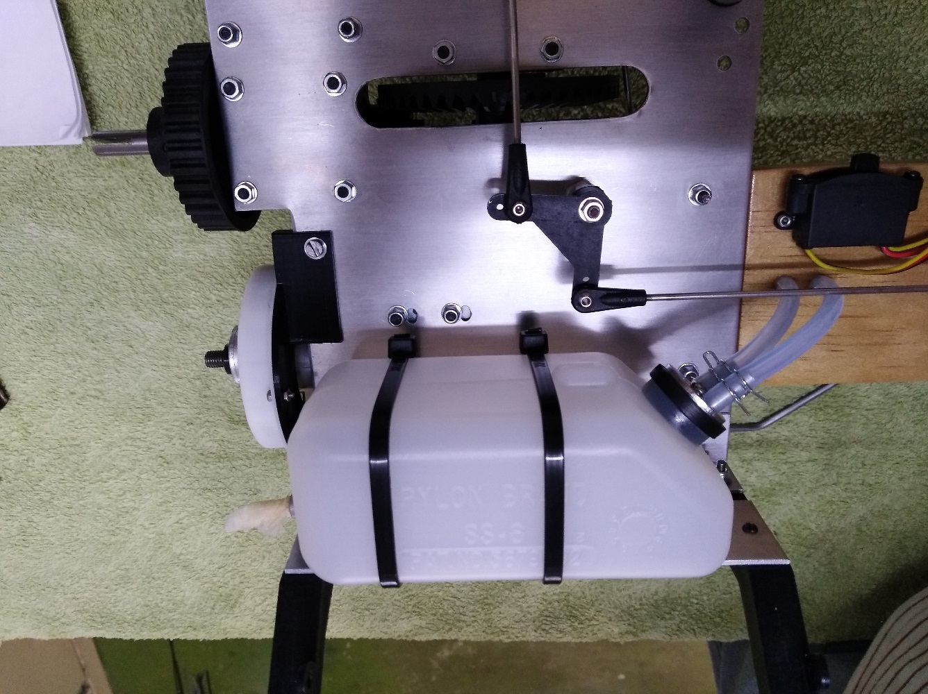
I do not have the original tank so used a Sullivan 8oz that was kindly donated by another club member - Thanks Reg!
Also, in the photos below, you can see part of the first version fan shroud/duct. This version doesn't quit fit right plus the final one will be printed in black.
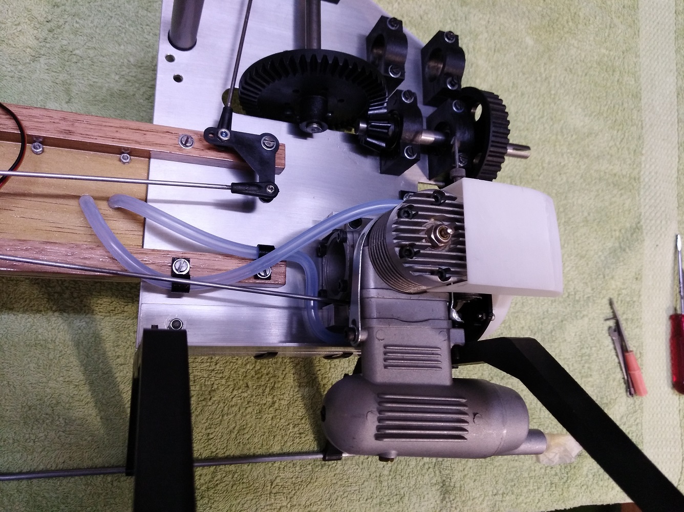
Fan Shroud:
Finalised the design and printed the Fan Shroud/Duct on a 3D printer. Couple of pics below.
My fan and ducting design seems to work ok as you can feel air pulsing over the engine cylinder head when the engine is idling.
The Kalt Baron I bought just recently had a good mechanical gyro that works well and is not too noisy. Seems appropriate, era wise, so it's going into the Tyke.
Its a Futaba FP-G153BB.
I've still to repair and paint the canopy and paint the tail feathers but that can wait until after initial flight testing is completed.
In the meantime, I'm about to start restoration of a Hirobo Falcon 555. Resto log here:
https://www.rcgroups.com/forums/show...5#post49931363
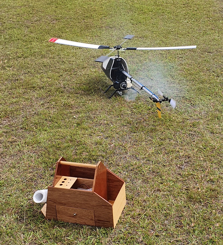
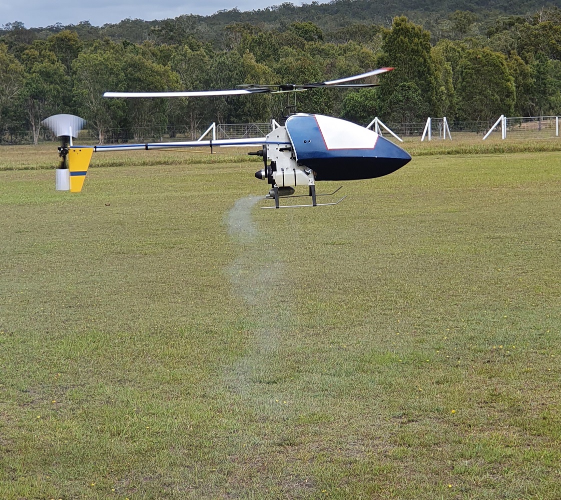
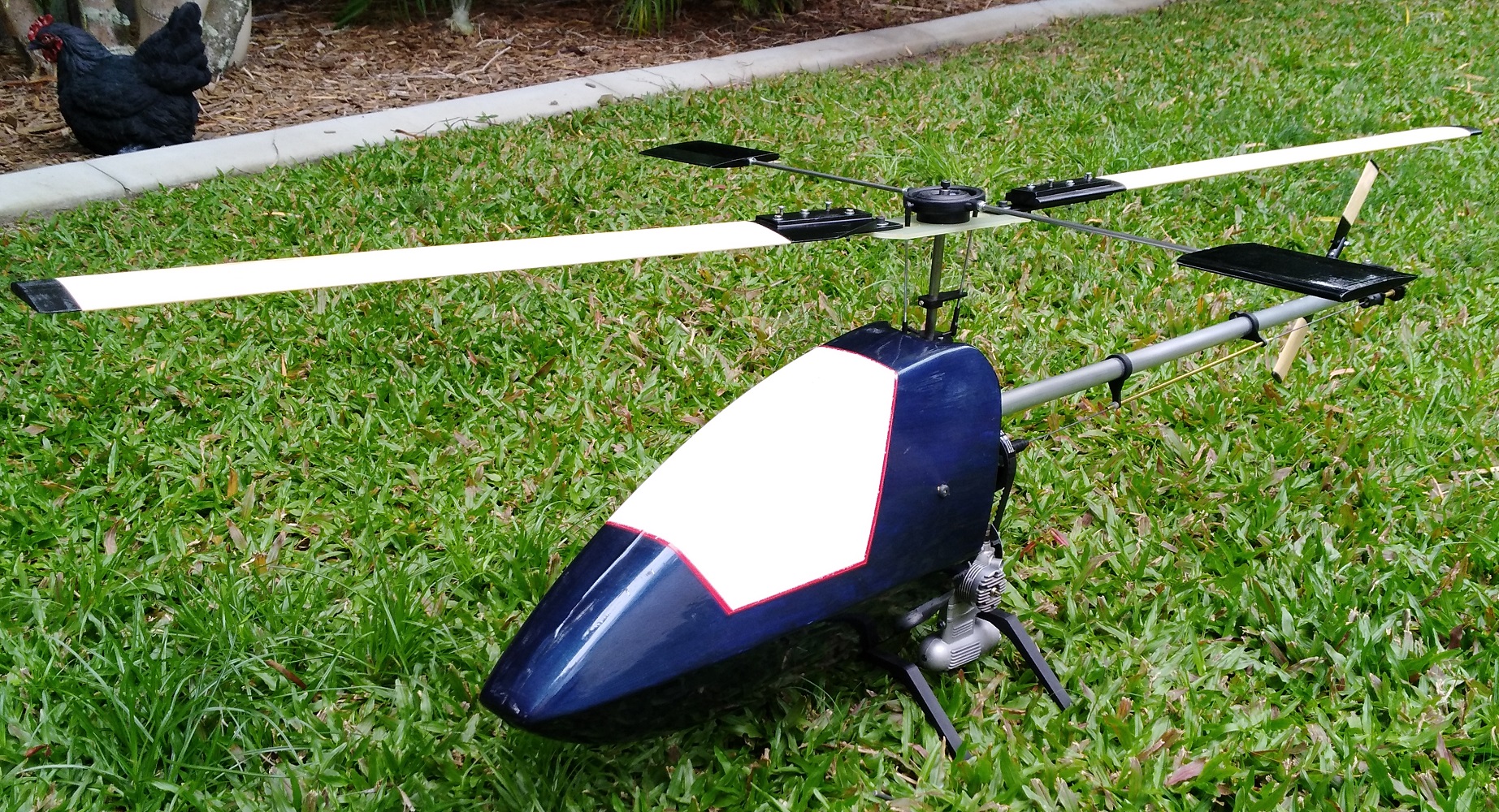
Found time to get to the club field this morning. Got the Tyke up into a hover, sorted out the tracking, sorted the way-out tail trim, sorted the over sensitive gyro setting and all was pretty good. Nothing fell off, came loose or broke. It does have quite a wobble which is made worse by the very flexible chassis so it will be back to the scales and hi-point balancer before the next flights. Then it will repairing and painting the canopy and tail feathers.
All in all, I'm quite happy.