Continuing our natural progression from the handle to the different types of control-line model that can be flown, there are a couple of other things that need to be considered.
The first of these is control surface hinges. There are many types of hinge available on the market, most of them designed for R/C models. Many of these will work satisfactorily on most C/L models. However, in many cases, the actual control deflection is greater and frequency of application is far higher. This results in a lot more wear than you would expect on an R/C model. A typical aerobatic control-line model will have an elevator deflection of 45 degrees up and down (sometimes more) and will be called upon to perform continuous sharp turns within a small area of sky.
One of the oldest forms of hinge is the fabric hinge (Fig.1). These are simply strips of fabric about 1/2" wide, glued to the surfaces in an over/under pattern as shown. If the right material is used, these will last indefinitely. Terylene is excellent for this purpose, so don't throw away those old terylene shirts. Polyester is adequate but not as good. Pure cotton is good but will eventually need replacing. Steer clear of all the modern mixes of any of the above, they are all inferior.
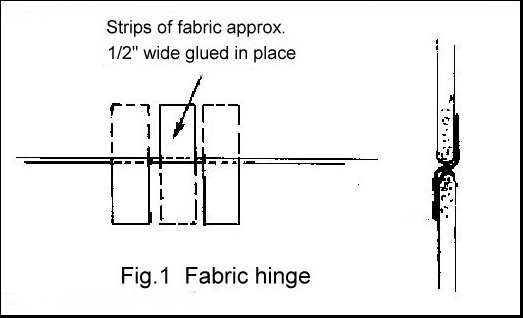
The biggest objection to this type of hinge is that they are difficult to hide and will stick out like a sore thumb on a good finish - not so bad if the hinge is neat, but neat fabric hinges require a special breed of modeller.
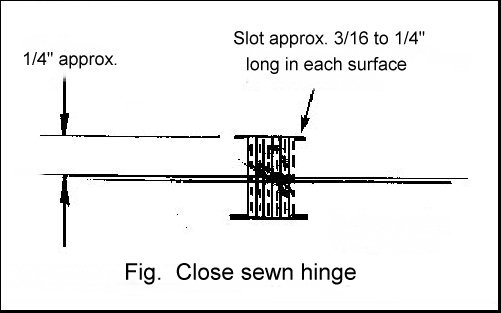
Potentially neater and probably easier is the sewn hinge (Fig. 2). This is simply a 'figure eight' pattern sown through the surfaces. The trick here is to mark out and make the holes in advance. The writer prefers a variation of this type (Fig. 3) which is much neater but harder to do. Instead of a row of holes, a slot about 3/16" long is made and around a dozen figure eight stitches made in that length.
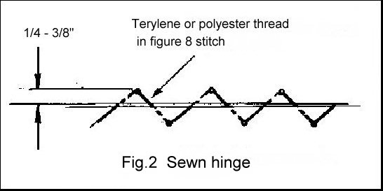
In either case, do the actually sewing fairly loosely and tighten it up by pulling on the loose end of the thread while working the elevator above and below the tailplane. This will pull everything up evenly. After securing the end, you can then finally align the two surfaces before applying glue either side of the hinge line. Don't use cyano - it will get everywhere and lock everything solid. The long-forgotten balsa cement is ideal for this. Again use pure terylene or polyester for the thread.
A whole book could be written on this subject. To some, it is akin to a black art and it is certainly true that the same tank will not work for everyone. All we can do here is to cover the basics.
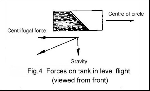
In level flight (as opposed to aerobatics), a control-line model is subject to two forces; gravity and centrifugal force. The first acts directly downward and the second acts outwards from the centre of the circle (Fig. 4). You may think that the latter acts outwards along the lines, but this is only true when the model is flying with the lines parallel to the ground. In other words, the model is flying at a height equal to the height of the control handle above the ground.
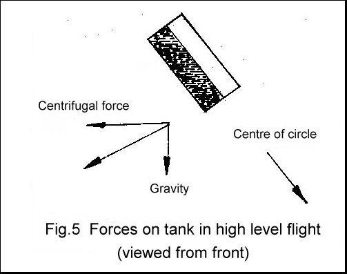
If the model is in high level flight, the actual centre of the circle is at the same height as the model, above the pilots head. Centrifugal force acts outward from this point and tends to become closer to the normal direction of gravity. Meanwhile, gravity itself becomes inclined inwards relative to the model (Fig. 5). The actual force acting on the fuel in the tank is a combination (or 'resultant') of the forces of gravity and centrifugal force and it should be clear from the above that this is rarely acting outward relative to the control lines. In most cases it is usually inclined upwards, or downwards, relative to the tank and in some cases may even be inclined inward. The commonly held belief that centrifugal force, along the lines, is the primary influence is far from true.
There is no place in this column for mathematics, but those who remember their physics will be aware of Newton's Laws of Motion. These all contain a constant, 'g'. This is caused by that 8,000 mile diameter ball of mud that we are all standing on. It's influence is far reaching!
With speed and racing models, where the model spends most of the time flying around in low level flight, the direction of this resultant force is fairly constant and the tank design can be optimised for this. There are several variations on the 'chicken hopper', or 'Marriott bottle' principle, involving specialised vent designs, which can be used here, though they are beyond the scope of this article.
When the model is required to perform aerobatics, things become much more complex. Both the centrifugal force along the lines and the force of gravity are generally less than the forces caused by the aerobatics. These consist primarily of inside turns (the imaginary pilot of the model is on the inside of the turn), better known as loops, or outside turns (pilot outside), better known as bunts. Here the requirement is mainly concentrated on the tanks ability to supply fuel in these two situations.
While the inside and outside forces are very similar, other factors can influence the flow of fuel. Therefore, it is normal to arrange for the vertical position of the tank, relative to the motor, to be adjustable, so that the inside/outside performance can be optimised. It is worth noting that, if the tank cannot be moved, the same result can be obtained by raising or lowering the motor.
Tank position can also be important when the model is in inverted level flight. Here again, it may be necessary to adjust the tanks vertical location to prevent the motor going rich or lean. That little 'g' rears it's head again.
The worst possible situation for fuel flow is where the model flies in a straight line directly over the pilots head (known as a wingover).
In the early days of C/L flying, frequent use was made of 'balloon tanks'. These employed a toy balloon to give a sealed tank which simply collapsed as the fuel was used up. As no air was allowed to enter, the feed pipe was always immersed in fuel and could pick it up in any attitude. This is an excellent arrangement but relies heavily on being able to find the right size of balloon, while the actual filling can be complex. A variation of this is used today in combat models and some speed models.
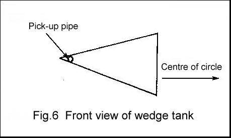
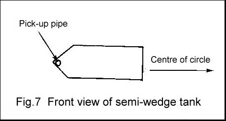
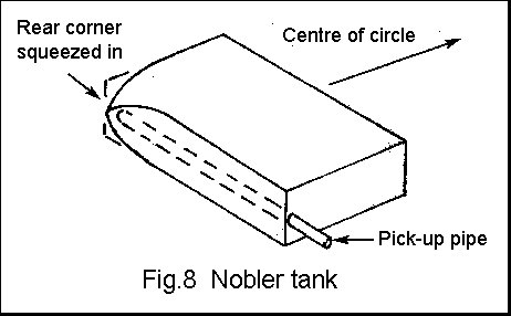
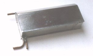
Next came the 'wedge' tank (Fig. 6). The idea was that the tank was essentially the same whether the model was flying the normal way up or inverted. In practice it is not really worth the trouble of producing a tank of this shape as, apart from being of doubtful value, it is difficult to fit into the model. If you want the tank to be easily removable (highly recommended) it makes things even more difficult. In most cases, a plain rectangle is quite satisfactory, although it is common to make the outer wall a slight wedge shape (Fig. 7). George Aldrich produced a tank for his 'Nobler' design which had the outer rear corner squeezed in the region of the pick-up pipe (Fig. 8) and this has become popular.
Many flyers use an adaptation of the commonly available plastic R/C tanks. Some, like the writer, find it difficult to achieve consistency with these - particularly where the motor run time is concerned. In the precision aerobatic event (FAI F2B) there is a small window between completing the schedule of manoeuvres and landing within the time limit. This can only be done by limiting the amount of fuel (no other method is allowed). Most tanks of this type are close to square in section. There are definite advantages to making the height of the tank as small as possible, so that the bulk of the fuel is kept as close as possible to the centre line of the motor and the effect of inside/outside turns is minimised.
The most contentious area of tank design lies in the venting arrangements. In reality, a vent has to perform just one function; to allow air to enter the tank to replace the fuel as it is used up. Ideally, it should also prevent fuel from running out when the model is being handled prior to starting the engine. Once the motor is running, this should not be a problem.
Mention has already been made of the 'chicken hopper' principal. Various claims are made for the use of certain types of venting which are said to produce this effect for tanks used on aerobatic models. If you are aware of the origin of this device - an automatic drink dispenser - you will be aware that they will not work upside-down and are entirely dependant on a consistent force of gravity applied from one direction. This is exactly what we don't have in our aerobatic control-line model.
One possible exception to this is where the vent is connected inside the tank to a flexible pipe with a weighted end, similar to an R/C klunk tank. The idea here is that the vent follows the fuel and tends to present a constant 'head' to the fuel. As the possible head variations here are substantially less than the possible head variations between the tank and the carburettor, the effects are limited. The type of model we are discussing tends to have a large powerful motor with a fairly small tank (for the reasons given above) and vibration can produce some strange effects due to klunk movement.
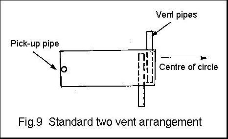
For many years, the convention has been to equip the tank with two vents (Fig. 9). The idea here was that one vent worked in the upright position and the other inverted. One possibility here is that fuel will siphon out of the vent which is immersed in the fuel. Facing both vents forward into the air stream will reduce this. Better still, block off one of the vents after filling. In fact, the system will work with just one vent and it is still quite practical to fill the tank by venting out through the feed pipe into the carburettor. This does mean, however, that you have to hold the model with the inner end of the pickup pipe at the highest point of the tank - not always practical.
If the above leads you to believe that the only really important fact about tank vents is that they should not let the fuel run out, you are dangerously close to the truth.
This being primarily a control-line column, we will not dwell on the curious practice of connecting the tank vent to the silencer in the mistaken impression that useful pressure can be derived from something with a hole in the back of it. What this will do is to introduce the products of combustion (primarily water) into the tank with disastrous results.
This is a very basic overview of the whole subject of tanks. We will return to the matter later in this series when dealing with specific types of model.
The whole business of flying a control-line model is a very personal thing. This is especially true of the matter of just how you manage to turn around at the same rate as the model without falling over.
Most flyers simply do what seems natural and develop their own way of getting along. There seems to be two basic methods; pivot on one foot or walk around in a small circle. The latter is by far the best for models that circulate at a comfortable rate - it's also lighter on shoe leather. There are even two ways of doing this; in front of the model, or behind it.
Things become much more difficult, and important, when you wish to fly a very fast machine. Some competitive speed flyers train for this by flying a small fast model on very short lines.
If you are new to the game, be aware that you will become dizzy (surprise!), but the effects pass rapidly and you will soon become used to them. Unfortunately, age does not help. Nor does a lack of practice. People who have returned to the hobby after many years have been known to circulate with a beatific grin on their face, land the model - and fall over.
Control-line has always been one of the more sociable sides of the hobby. Despite this, it is possible to fly alone. Yes, I know that this is frowned upon these days on safety grounds, not only from your own point of view but also because of the danger to others. Do be aware of the fact that passers-by may not be aware of the danger and try to keep well away from others. Ideally, only fly alone on an area which is well established as a control-line flying site. If in doubt, don't do it.
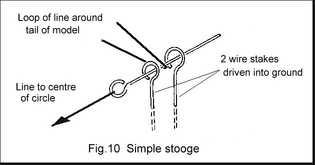
What you need is a 'stooge'. The simplest consists of three pieces of wire with loops in the end. Meat skewers are excellent if you can find any. Two of these are pushed into the ground and the third is used as an anchor (Fig.10). A length of line (string, control-line, or my personal favourite insulated hook-up wire) is laid out into the circle along with the control-lines so that you can release the model. A loop of string around the tail completes things.
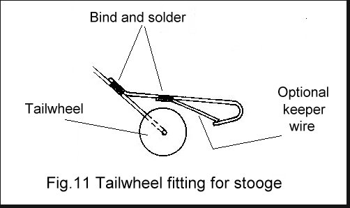
Sophisticated versions include custom attachments on the tailwheel to fit the stooge (Fig.11), while the stooge itself can even extend to a large sheet of ply to stand the model on with a self-contained release mechanism.
Wherever you fly, be it alone or in groups, keep well away from overhead power lines. High Tension electricity can jump enormous distances under favourable conditions and the model does not have to touch the wires to produce serious, or fatal, injuries.

![]()
![]()
![]()
![]()
![]()
![]()
![]()