When the editor of 'Aviation Modeller International' asked me to do a series of articles on control-line flying, I wondered just where to start. That conversation lasted quite a while and most of it was about control handles, so the question really answered itself. Where better to start than at the pilot's end of the whole system - the handle. I apologise here and now for the number of times the word 'handle' appears in the following - there's simply no substitute.
Maybe we should pause a moment here to explain just what we mean by 'control-line'. This a method of flying model aircraft where the model is tethered to the pilot and flies around him. Two tether lines are used (there are other systems) and movement of the lines relative to each other moves the models elevator control surface up and down. Thus, one line is the 'up' line and the other is the 'down' line. Small movements of the lines produce small elevator movements. Various descriptions have been coined by those who haven't tried (or tried and failed at) this type of flying, such as, "Bricks on strings", etc. Personally, I rather like, "Yo- yo's".
Back to the plot. Even today, when most of the modelling community tends to look upon C/L flying as a lost art (I think 'art' is the word they use), you can still usually find a control handle in model shops. The biggest part of the problem here is usually to find a model shop! Basically, it consists of a handle shaped to fit within the clenched fist, with a fitting at each end (actually, the top and bottom) for the control lines (Fig. 1).
The models that are flown with these handles come in all weights and sizes and fly at all kinds of speeds, so this simple device can actually range from a plastic moulding, as seen supplied with some ready-to-fly models, to a hefty and substantial piece of engineering. The most commonly seen commercially produced item usually consists of an aluminium casting with an adjusting screw at one end.
Note here that it is not a good idea to pick up the device the wrong way round. If the handle is upside-down, the control will be reversed, usually with disastrous consequences. Ideally, the shape should make it impossible to do this, but this is rather difficult to accomplish. I have heard quite heated arguments as to which way a particular commercial item is meant to be held. This is easier if you make the handle yourself, but the best arrangement is to mark one end in some conspicuous manner, or colour (stand by for an argument on whether the 'up' or 'down' end should be marked!).

You could be forgiven for thinking that the above description is just about the end of the story, but there is far, far more to it than that. We have already mentioned that one of the end fittings is usually made adjustable so as to vary the centre, or neutral, of the available control range. With this you can adjust the attitude of your hand when the model is in normal level flight so that you are comfortable. This can also allow you to compensate for any variation in the length of the two lines relative to each other. There are many ways of doing this and many home-made handles use a heavy, flexible cable passing through the handle with a clamp at it's centre (Fig. 2).
While this can certainly be useful, it is actually possible to dispense with this adjustment by carefully making up the lines and ensuring that the control system in the model is completely symmetrical. Indeed, this writer dislikes this form of adjustment on the basis that it is something to go wrong and much prefers to make any adjustment by adding spacers to the line, or handle.
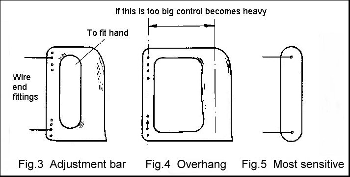
Far more important in many peoples minds is that the actual spacing of the lines at the handle should match the system in the model so as to give the right sensitivity, or 'feel'. This too can be done in many ways, the simplest being a handle with a bar across the front of the hand with a series of holes, giving a range of available spacings (Fig. 3).
Of almost equal importance, but usually ignored, is the 'overhang' on the handle (Fig. 4). This can be used to give a form of fine adjustment to the models sensitivity. A lot of overhang (more than, say, 3 inches) will give the model a 'dead' feel, due to the effort needed to apply more than a small control movement. Depending on the weight of the model, and other factors, this can be surprisingly effective. Many years ago, this writer used to use a handle which was no more than a vertical bar with the line fittings at each end (Fig. 5). This meant that the model could actually be controlled with the fingers, giving a very sensitive control.
Most people find that they are more comfortable if the 'neutral' attitude of the handle is tilted forwards. If you clench your fist and hold your arm straight out in front of you, you will almost certainly find that the fist is tilted forwards. Many commercially produced handles incorporate this to some extent, but usually only a small amount. Your personal physiognomy may well prefer more.
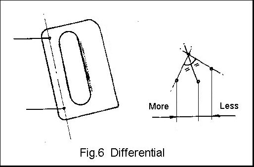
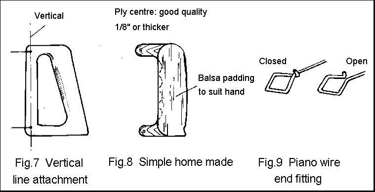
There is a problem lurking here that is not at all obvious at first sight. Tilting the handle forwards introduces differential into the control response, giving the effect of reduced 'down' movement (Fig. 6). Once you are aware of the problem, the cure is simple. Increase the length of the lower handle fitting to bring the line attachment points back into vertical alignment (Fig. 7).
The writer has always been aware of his preference for some forward tilt on the handle and, for many years, simply tilted the handle forwards until comfortable. Despite being aware that all his models seemed to turn better in the 'up' direction (inside manoeuvres), the connection with the handle attitude was never made.
A few years ago, an accident led to a severely dislocated right index finger. The result of this was that it is no longer possible to tightly clench the whole fist. That finger simply won't fold right round. This led to a whole series of problems in getting models and lines set up correctly. It wasn't until a large degree of tilt was actually built into the handle that the problem was solved - but outside manoeuvres still posed a problem until the need for vertically aligned line attachments was realised.
It must be stressed here that this is a matter of comfort. Any competent flyer can fly a model with just about any handle, but there may be problems that are difficult to pin down. If the handle/lines are seriously out of trim, it is possible to compensate by holding the handle at its top or bottom, but you will not be able to fly to the best of your, or the models, ability.
One final factor is the weight of the handle itself. The writer likes a very light handle. Most commercial types are fairly heavy. Some pilots like a heavy handle, it's all a matter of personal preference.
We now have a set of requirements for our perfect handle, which may seem to be contradictory in some respects. If we need to offset the body of the handle from vertical as discussed above, this is a constant factor which can be established for the individual.
There are many ways of producing a handle which can allow adjustment of all of the critical dimensions and you can even buy one from specialist suppliers. Making one yourself is fairly straightforward. The alternative, and possibly easier, solution is to make a handle to suit the model. This could mean making several handles before you are satisfied, but experience will shorten the process considerably. If you follow this route, never throw a handle away, it might be just right for the next model.
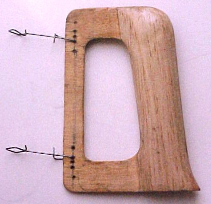
Taking the simple route first, the main part of the body need be nothing more than good quality 1/8 inch plywood, though 2 layers of 1/16 is better. Layers of 1/4 or 3/8 inch balsa can be used to build up the portion which fits inside the hand and this can easily be fashioned to a comfortable shape. The end fittings are of piano wire which need be no more than 18-20 swg (Fig. 8). For durability, rub cyano or epoxy into the wood and paint with any convenient paint in a bright colour. It's amazing how well these things can hide in grass.
The next stage is to incorporate adjustable line spacing by adding a bar in front of the hand (back to Fig. 3). This bar actually serves a second purpose. When I used to fly C/L Combat (more on that in a later article) I used this type of handle because it allowed me to change hands more easily. This was very useful as a means of avoiding tangling lines with my opponent. One possible problem here is that the bar adds overhang, which you may not want.
Before we go on to more complex types, it's worth talking about those end fittings. Many people simply terminate these with a closed loop and then use an additional connector (there are many types of these available from those specialist suppliers) to attach the lines themselves. This is a system that I hate. There is simply too much to go wrong! The best approach is to incorporate the connector into the end attachment. Fig. 9 shows a system that I have used for some 50 years with no problems. A similar system is used at the model end. I have never tested the ultimate strength of this design, but the most that has happened is that the odd one has stretched slightly when subjected to a very high load.
 Just the handle and the line.
Mention has already been made of using a continuous cable (back to Fig. 2) with a clamp at its centre. The cable needs to be fairly hefty. Something like cycle brake cable is ideal. Anyone remember 'Bowden' cable? The locking device needs to be a wingnut or similar. It needs to be fairly easy to adjust and lock the lines, but be aware that too easy means it may 'adjust' when you don't want it to.
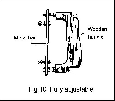
The 'ultimate' handle is something like Fig. 10. Here it is possible to adjust both the spacing and the overhang to suit your needs. Here again, it is possible to buy such a device, but you need to hunt around. I recently saw one of these made up from the handle of an old tenon saw. Interesting here that saws have that previously mentioned forward tilt built in. From my point of view, though, all of these are just too heavy.
Why do I place a premium on the weight of the handle? Because I prefer models with very free control systems which can be be fully controlled even when the lines are slack. A heavy handle gives virtually no 'feel' under these conditions.
This may seem like a lot of trouble to go through to produce such a simple device, and you may well be right. The human brain can learn to do just about anything, especially the hard way. If you take your control-line flying seriously, try doing it the easy way. The 'good' flyers (it's all in the mind) learned all this years ago.

![]()
![]()
![]()
![]()
![]()
![]()
![]()