In the first part of this series, we mentioned that there were other ways of controlling the elevator on a control-line model than the normal two line system. In the early days, one method was to attach a single line from one wingtip of the model to a pole and to simply control the height of the model by raising and lowering the pole. This was used both for powered models and unpowered ones which were simply 'whipped' around.
Eventually, this led to a more sophisticated system where the line was twisted to move the elevator. One disadvantage of this method is that you must use a single strand line, multi- strand lines won't work. An advantage of this system was that full control could be maintained when the line was slack and it was possible to fly on a very long line. Later, this idea was used to some effect on speed models, which could go considerably faster than with two lines due to the reduced drag. This was later banned for international events in an attempt to reduce speeds. It is still used for some specialist classes, but the equipment is not easy to make yourself and commercial equipment is no longer available.
The two line system which has become standard was introduced in the USA by Jim Walker, who patented the idea. For many years, kits for C/L models did not detail the control system to avoid paying royalties. A common note on the plans said, "Install your favourite control system here." At least one British kit showed the system in detail, but referred to the bellcrank as a 'fulcrum'.
Things were thrown open, in a subsequent legal action, by the revelation that Mr Walker had actually borrowed the idea from someone else. Substantial damages were awarded!
The heart of this is the bellcrank (Fig. 1) which is mounted somewhere adjacent to the centre of gravity of the model. It can actually be mounted anywhere, but practical considerations tend to limit it's location to within a fairly limited area (more anon). More often than not, it is mounted inside the model, but it can be simply hung on the outside in the airstream. It is possibly to produce a very simple model with just about everything hung on the outside if you wish. Taken to it's logical conclusion, all you need is a plank of wood with an engine on the front, an elevator on the back, three pieces of wire and a bellcrank!
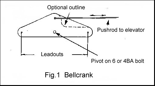
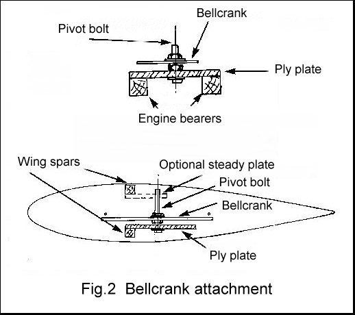
This bellcrank is mounted on a pivot, which is typically a 6BA or 4BA (3M or 4M) bolt. This bolt needs to be securely anchored to the airframe and is normally attached to the mainspar or the engine bearers (Fig.2).
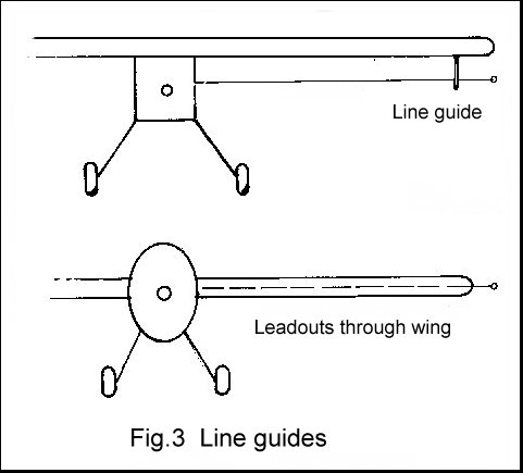
Two lines extend from the bellcrank to the inboard wingtip of the model. These are then attached to the control lines from the control handle. You could simply attach your control lines directly to the bellcrank if it is accessible, but it is then necessary to have some sort of line guide at the inner wingtip to stabilise the model laterally (Fig. 3). Normally there are two lines (known by some devastating logic as 'leadouts') extending through the inboard wing from the bellcrank and emerging from the wingtip, where the control lines are attached.
Returning to the bellcrank (Fig. 1), a pushrod runs from it to the elevator control horn. Thus, relative movement of the two control lines moves the bellcrank and, in turn, moves the elevator. The sheer simplicity of this arrangement means that everything can be easily home- made, with the result that all competing methods fell by the wayside long ago.
There is a more sophisticated version of this system incorporating a 'circular bellcrank'. This will be dealt with later in this series.
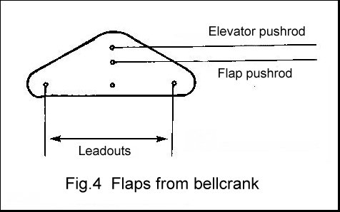
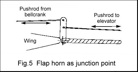
For reasons which we will attempt to cover later in the series, it has become customary (I almost said 'fashionable') to equip aerobatic models with moving wing flaps. These move in the opposite direction to the elevator ('up' elevator gives 'down' flap and vice versa) and require an additional linkage. This can be in the form of an additional pushrod from the bellcrank (Fig. 4) to a flap control horn, or by using the flap horn as a junction point (Fig. 5).
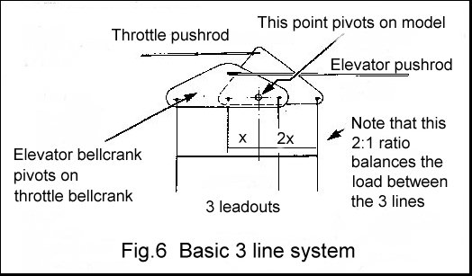
If you wish to operate additional simple controls such as to trigger a bomb release, on a scale model, it is a simple matter to add an additional line to operate this. If you wish to have full control over this function, such as for a throttle control, then better results can be obtained by using some form of balanced system where the load is spread between the control lines and the additional line.
There are several ways of doing this and commercially produced equipment is also available. The simplest system is shown in Fig. 6. This merely shows the basics and many articles have appeared which describe variations, and improvements, so we will not go further at this point. More information is available from the UK Carrier group. Details at the end of this article.
On the face of it, these are the simplest part of the system, but they tend to produce more argument (sorry - discussion) than most of the rest of the system put together. The first question is, solid or stranded?
Many people prefer stranded wire leadouts, if only because it is so easy to bend solid wire at the point where it leaves the wingtip, resulting in weakness. It is hard to disagree with this but the solution is simply one of taking care in transport.
The problem with stranded leadouts, from the writers point of view, is that there is the question of just how to make up the ends, particularly at the bellcrank, where wear can be a problem. In most cases this joint is hidden away inside the model and fairly inaccessible. Probably, the best solution would be to use solid wire (piano wire) for the section that goes through the bellcrank and then join the stranded wire to it. A soldered joint may be the solution, but I've already said I don't like those. Any kind of connector at this point (similar to those described in the handle article) means another bit that you can't see and check on.
Another problem is that it becomes necessary to introduce another connector at the outer end in order to attach the control lines.
If you want to do things that way, go ahead, many people do. However, the writer's recommendation is that you use solid wire just like an extended version of the connector described in the article on handles.
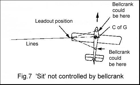
Mention has been made of practical considerations influencing the position of the bellcrank. One of these is the need for the leadouts to exit from the wing, or line guide, without any misalignment causing bending or binding (Fig. 7). The actual 'sit' of the model on the end of the lines is a function of the line guide position and the models centre of gravity position. Ideally, the bellcrank needs to be positioned so that the lines exit from the model in a straight line.
All of this has a distinct effect on the behaviour and trim of the model and many flyers now prefer to be able to adjust the position that the lines exit from the model. If the leadouts are external to the model, this can be catered for by having several holes in the line guide. Internal leadouts, however, need to have some form of adjustment built into the model during construction.
Many published designs show a fixed position for the leadouts to exit from the wing. In most cases this is perfectly satisfactory. In any event, a less than perfect position is far better than an adjustable system that can move when you don't want it to.
Some years ago, the great Bill Netzeband wrote an article in an American magazine which gave a method of calculating the correct position for the leadout exits relative to the models centre of gravity. He showed that, for a given model, the only thing that actually affected this was the models airspeed. In other words, if the speed doesn't change and you don't move the C of G, there is no need to move the leadout exit point.
From this, it would seem to follow that any well proven design should manage perfectly well with the leadouts fixed in the position shown on the plan. It is also worth pointing out that a Vintage, or Classic design with adjustable leadouts is no longer, technically, vintage or classic.
When control-line flying was in it's heyday, you could purchase bellcranks in a range of sizes and materials. One common material was 'Paxolin'. This is/was a paper based phenolic material which was commonly known to fail at the holes. There is a vastly superior material which is fabric, rather than paper, based and known as 'Tufnol'. This is fine, if you can find any.
Another common material was dural, which could wear quite badly at the holes for the various control wires. This is fine for a light model. Don't be tempted to use aluminium.
You can still obtain nylon bellcranks from specialist sources. SIG (see last month) produce a 4 inch example (four inches between the leadouts). This is an excellent material and the writer has old nylon bellcranks which have been recycled through several models. A personal favourite is the 3 inch bellcrank produced by Frog some 35 plus years ago.
Good quality plywood is almost as good as nylon and has the advantage that you can make any size that you want. The writers preference is for two layers of 1/8 inch ply, laminated with epoxy or slow cyano. If you can find 5 ply rather than 3 ply, so much the better. You can bush the holes with brass tube if you wish, but this is not really necessary. It helps a little if you soak the area around the holes with cyano.
A plywood bellcrank will wear to some degree but most of the joints are in tension during flight so slop is not a problem. The only exception to this is the hole where the elevator/flap pushrod exits. However, this is not subject to the sort of loads that the pivot point and leadout holes are and wear is much less. Contrary to some opinion, a certain amount of slop is not a bad thing anyway, since it will make the model less sensitive in level flight. Old models don't 'hunt'.
The ideal bellcrank material is glass reinforced plastic (GRP) which is normally used to make printed circuit boards. It is available in various thicknesses, but 1/16 inch is ideal. However, be aware that some older material used for this purpose is actually paper-based and is no better than paxolin. The glass-based version is fairly easy to identify since you need a good quality saw to cut it. It doesn't matter if it has copper on one side.
These are normally made from fairly thick piano wire to avoid any tendency to bend, or buckle. It is becoming usual these days to use GRP tube (arrow shafts) or even carbon fibre rod or tube. In this case, you need to use piano wire at the ends and you come up against the same problem of how to make the join. For all practical purposes, wire is still the best.
Use at least one guide at some point between the ends of the pushrod. This is not so much to avoid any buckling of the rod, but more to stop excessive vibration. Vibration can cause rapid wear of the holes in the bellcrank and control horns. Rather than spending lots of time trying to make a hole of the right size and position in some intermediate former, make an oversize hole with adequate clearance. When the controls are complete and working, add strips of balsa to limit lateral, and vertical, movement of the pushrod to the minimum amount required.
Yes, you guessed - it used to be possible to buy a range of horns and some are still available from those specialist suppliers. In most cases, these consist of a brass, or steel, horn brazed, or silver soldered to a wire joiner. The joiner is then attached to the control surfaces. If you make your own, never use soft solder.
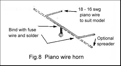
I've never known a commercial horn of this type to fail (where's that piece of wood?) but I have never trusted them! My preference is for the 'vintage' type of horn which is bent up from wire (Fig. 8). With care, you can produce an excellent fit onto the end of the pushrod and have a slop free joint which will last forever.
This is way outside the range of this article but needs to be mentioned. Those two basic control lines can be used to make a circuit. This circuit can be used to transmit information. In it's simplest form, you could drive a motor to perform some function, though voltage drop will severely limit the power that can be transmitted.
With modern technology, the circuit can be used in place of the RF link in a radio control system. By using an encoder at the handle end and a suitable decoder in the model (with on- board battery supply), you can have proportional control of several R/C servos.
Who will be the first to use an 'active' elevator?
Some UK suppliers still offer a small range of C/L items and they should be available from your local model shop. The biggest UK supplier is Irvine Engines (Tel: 0181 631 1123). They produce a catalogue showing all the items that they handle.
There is a large 'cottage industry' of specialist suppliers worldwide. A list of these is beyond the scope of this article, but a selection can be found on my links page here
More details of 3 line control systems can be obtained from:
Andy Housden, 8 Denmark Road, Kingston upon Thames, Surrey. KT1 2RU.
Tel: 0181 541 0186.
Andy produces a Carrier information pack which can be obtained from him or at any C/L Carrier meeting. All of this information can also be found on the UK Carrier website at: http://www.cheffers.co.uk/carrier.html
