Try sneaking up on it! - You can't break it! - One step at a time - Travel adjust - Dual rates - Exponential - Sub trim - Throttle hold - Throttle curve - Idle up - Pitch curve - Summary of pitch and throttle options - Revolution Mix - Failsafe - Low battery warning - So much for 'Function Mode' - Remember 'System Setting Mode'? - If you have got this far
It must be very obvious, to anyone who has been paying attention, that the R/C world - like most things - is being taken over by the computer. In a very short time it will be impossible to buy a new set of radio gear which is not computerised to some degree. OK, that old faithful set has been serving you for many years and you don't see the need to change yet. Fine, but nothing lasts forever. Some day you will have to buy a new set and the chances are that, at the current rate of progress, things will have advanced far enough to make present day sets look very simple.
Personally, I view the introduction of the computer to the R/C world as a very good thing. Even the most basic of sets can now do things which were undreamt of only a few years ago. A new computerised transmitter represents an enjoyable challenge and I find it hard to imagine why some people don't like them. Having said that, I must admit that some of the cheaper sets can be quite intimidating at first sight!
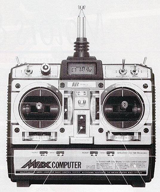
A good example is the JR 'Max' series. These are designed as 'budget' sets, which means that the designers have had to make a lot of compromises in order to make the most of the facilities available without the use of expensive display units, or lots of pushbuttons. The result is like a very complicated wristwatch and the user has to do a lot of learning before he can make full use of all that it has to offer.
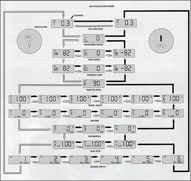
Keeping the price of the display unit within reason means that most of the functions have to represented by codes, or abbreviations, while limiting the number of pushbuttons means that the various functions can only be accessed in a particular order. To this end, the instructions include a 'flow diagram' which guides you around the system. This is fine in the comfort of your fireside, but to make full use of it on the flying field you need to memorise the main features.
Does this sound too intimidating so far? If so, remember just how much you had to learn when putting together that first aircraft, or helicopter.
I'm going to assume that you are already familiar with the controls of an R/C transmitter and know what they do. If not, this article will be beyond you anyway.
You should realise straight away that you don't need to understand, or even use, the computer part of the set in order to fly your model. You can simply switch the transmitter on and use it just like any other non-computer set. Those of us who have been in the hobby for some time will remember when such things as rate switches, servo reverse and travel adjust simply did not exist and we managed quite well without them. A computer set can be used in exactly the same way.
In this condition, on a helicopter set, the throttle hold and idle-up switch will not work. If you are in the process of learning to fly, this will not present any difficulty, since you don't need them yet.
The message here is that those who are just starting out can buy a computer set and learn how to use it later, while those who have been around for a while can use it just like their old set and learn to use the extra facilities later. For those who are afraid of computer sets, or reluctant to try one, I hope you are beginning to realise your mistake!
Having got over that hurdle, let's continue the process we have started and try to explain the 'Max 6' helicopter set in more detail. The first thing to do is to switch on the transmitter - this may seem obvious, but read on - and see what we can learn (the on/off switch is in the middle of the front panel and it moves up for 'on').
The display will show 'C7BATT' and the battery voltage, which can be anything between 11.2v and 9.0v, if all is well. In this state, the set will work normally and none of the 4 pushbuttons will produce any response if pressed individually. Incidentally, the 'C' means that the transmitter will only work with a PCM receiver. If it says 'F' instead, then the transmitter will only work with a normal FM receiver. The '7' means that this is a helicopter set ('6' means that it is an aircraft set).

As a first move in getting acquainted with the computer part of the transmitter, let's see just what you have to do if you want to change from the PCM to the FM mode (see above).
With the transmitter switched 'Off', hold down the two pushbuttons labelled [UP] and [DN] together and switch 'On'. This puts the transmitter into what is called the System Setting Mode and allows us to do one of 3 things. These three things can be stepped through by using the [UP] and [DN] keys singly.

Only one of the three need concern us at this stage and this one is indicated by the display showing 'FN1' and either 'C' (PCM) or 'F' (FM). You can change from one to the other by pressing either the [INC+] or [DEC-] button.

When you are in the System Setting Mode, the transmitter will not operate the receiver. Normal operation can be resumed by pressing the [UP] and [DN] buttons together ('ENTER') or by turning the transmitter 'Off' then 'On' again. That was quite painless wasn't it?
When you begin to feel a little more adventurous, the next stage is to press the [UP] and [DN] buttons together with the transmitter already switched on. This puts it into the Function Mode and lets you set up all of the various controls to suit your particular model. If you are able to follow the 'Flow Diagram' in the manual, you can now select any function by means of the [UP] and [DN] buttons. The [UP] button steps through in the order shown by the black line, while the [DN] button steps through in the order shown by the white line.
If you cannot follow the diagram, don't panic, try it another way...
The most likely thing that the average modeller will want to do is to reverse the direction of a servo. Do it this way:
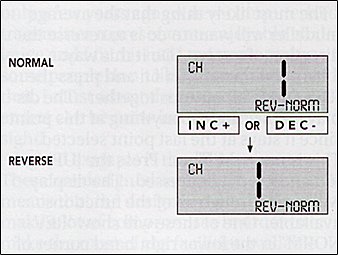
Turn the transmitter on and press the [UP] and [DN] buttons together. The display can say almost anything at this point since it stays at the last point selected. This is not a problem. Press the [UP] button and keep it depressed. The display will cycle through all of the functions available. One of these will show 'REV-NORM' in the lower right hand corner of the display. This is the one you want. If you missed it first time, keep pressing until it comes round again. It will also show 'CH' in the top left hand corner and a number '1' to '6'. If the number is '1', the [UP] button will step through to '6'. Don't press the [DN] button, it will take you to another function! If the number is '6', the [DN] button will step through to '1'. Don't press the [UP] button, it will take you to another function! If the number is between '1' and '6', the buttons will step in either direction.
It is worth repeating this in a different form, since it is an essential part of most adjustments. If you have selected any function and the channel number displayed is between '1' and '6' ('2' to '5') the [UP] and [DN] buttons can be used to select the channel that you want. If channel '1' is shown, the [DN] button will take you to another function. Likewise, if channel '6' is shown, the [UP] button will take you to another function.
The problem here is in knowing the number of the channel which you require. You won't find this information in the manual! The easiest way to check is to look at the label on the receiver sockets and count along to the one you want. The order is:
1 Throttle
2 Aileron (lateral cyclic pitch)
3 Elevator (fore/aft cyclic pitch)
4 Rudder (tail rotor pitch)
5 Gear (or gyro gain)
6 Pitch (collective pitch)
Having found the channel that you want to reverse, pressing either the [INC+] or [DEC-] button will move the channel number in the display from the 'NORM' to 'REV' position (or vice versa) to indicate that that channel has been reversed.
Yes, it does sound like quite a performance to reverse one channel, but it is amazing how soon you get used to doing it and how your confidence will grow each time. The basic process of selecting Function Mode, then the function and channel that you want is the same for all of the adjustments that relate to each separate channel.
While you are in the Function Mode, the transmitter will still operate a receiver and work normally. Any changes that you make will take effect immediately. This means that you can leave a particular function selected for as long as you need to make any necessary adjustments. Simply switching off will store that adjustment without any other action.
Travel adjust (or adjustable end points) means changing the amount of movement of any of the models controls for a given movement of the control stick or knob. On the 'Max 6', the actual travel for full movement of the stick can be any value between 0% and 160%. To be strictly accurate 'travel adjust' would change the amount of travel in both directions (from the centre, or neutral) simultaneously. Most modern equipment, including the 'Max 6', allows you to set the travel in each direction separately. For example you can have more 'up' elevator than 'down'.

This is the one which causes the most trouble and it is all because of that little % sign which appears at the top right hand corner of the display. It is an abbreviation for 'percentage' and all that it means is 'parts of the whole', with the 'whole' being 100. Or, if you like, marks out of 100! So the 'normal' throw is 100% In this instance you can have more than 100% if you wish and the maximum available is 160% or slightly more than one and a half times normal.
However, we are getting ahead of ourselves. Turn the transmitter on and press the [UP] and [DN] buttons together. Hold down the [UP] button until you see 'T.A' appear in the bottom left hand corner of the display. This will be accompanied by 'CH' at the top with a number from '1' to '6' below it and a percentage (usually '100%'). You can select the channel that you want in exactly the same manner as described above for channel reversal. Having done so, the throw can be increased or decreased by means of the [INC+] or [DEC-] buttons. Pressing both buttons together ('Clear') will return the value to '100%'.
Note that you can set different throws in each direction of each channel (different 'end points') and that this is automatically selected by holding the appropriate stick or control in the desired position. Let's try that again. Select channel 1 and hold the throttle stick in the fully forward position. Set the required throw with the [INC+] or [DEC-] buttons. Pull the stick to the fully back position and note that the value now changes to '100%' (or whatever was previously set). You can now set the required value for the lower stick position.
Returning to the matter of understanding and visualising what is meant by 'percentage'. If the value is set to '50%', the throw will be halved; if it is set to '25%', the throw would be reduced to one quarter. '33%' would give one third, etc.
This business of percentages becomes of more importance when we want to use the rate switches.
What this means is that by operating a switch we can change the amount of movement of a control surface for a given stick movement. Assume that the aileron travel adjust is set to normal (100%), and that the upper position of the rate switch is set to give normal throw (100%), while the lower position is set to give half the normal movement (50%). When the switch is moved from the upper to the lower position the aileron travel, for full stick movement, will be halved. The model will then be much less sensitive to control applications.
An example of this would be on a model helicopter where the use of maximum control throws is needed for aerobatics with much less throw being used for smooth hovering flight. In general terms, the upper switch position gives 'full rate' and the lower position 'half rate'. Hence 'dual rates'.
So, go through the now familiar process described above until the display shows 'D/R' between the channel number and the percentage. Note that you can only get channel '2', '3' or '4' (aileron, elevator or rudder), since dual rate is only available on those channels. Clever things these computers, they even do your thinking for you!
Put the appropriate rate switch in the required position and set the percentage figure to the one required by means of the [INC+] or [DEC-] buttons. Now move the switch to the other position and set the rate required in the same manner. Note that the display automatically shows which rate is selected by the switch and each position can be set to any figure between 0 and 125%. Neither has to be 100%, and either position can be the 'high' or 'low' rate.
Actually, the 'Max 6' does not have a rudder rate switch, but the software (that means the computer 'program') makes provision for it. You can use it as another way of increasing, or reducing, the rudder travel.
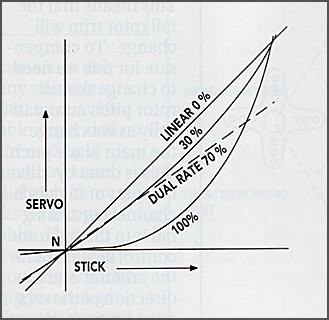
This allows the sensitivity, or 'rate', to be increased progressively as the stick is moved further away from the centre. In a helicopter it can be used to give smooth hovering control for small stick movements and coarser control on large stick movements for aerobatics.
Follow the usual route until 'EXP' appears in the lower right corner of the display. Once again, only channels '2', '3' and '4' are available. The display will show 0% indicating that the response is linear. Using the [INC+] or [DEC-] buttons will change the percentage as required. More percentage means more exponential. 100% exponential will give no control movement at all for small stick movements with a dramatic increase in sensitivity as maximum movement is approached. How this control is used is purely a question of individual preference.

Note that the exponential works in addition to the dual rate facility. If you have, say, 50% rate, you can still have up to 100% exponential on that rate. The rate switch also works and you can have different values of exponential on the two positions. Like the dual rates, this is set by putting the switch into the appropriate position and then using the [INC+] or [DEC-] buttons.
Available on all 6 channels, this offsets the centre in exactly the same way as the stick trim levers do.
Go through the functions in the usual way until 'S.TRIM' shows at the bottom of the display. Select the channel you require as previously and set the value you want with the [INC+] and [DEC-] buttons. The maximum is 125%, which is roughly the same as full normal stick travel. Note that the figure can be positive or negative, which decides the direction of trim. To get the actual direction that you need, you will have to experiment. There is a pattern, but explaining it will take longer than discovering it for yourself. Treat it as a useful learning exercise.
Note that with normal, or reduced throw, 125% sub trim offset will mean that full control deflection will not be available. This effect can only be avoided when increased throw is in use, otherwise the amount of sub trim available is limited. The moral is 'use with care and check the effect'.
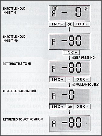
This freezes the throttle channel at a preset point while leaving the pitch channel still under the full control of the throttle stick. Here the intention is to either stop the motor for autorotation landings, or set the motor to a low idle so that you can practice autorotations.
Go through the usual routine until the display shows 'FNA'. If the hold switch is inhibited, this will be accompanied by '-0'. Using the [INC+] and [DEC-] buttons will vary this figure between '+125' and '-125'. This is the full range of the throttle stick with '0' (not '-0')being the centre. By this means, the hold switch can freeze the throttle at any point. Pressing the [INC+] and [DEC-] buttons together will return the hold switch to the inhibited state. The [INC+] or [DEC-] button will return the switch to operation at the previously set value.
By this means you can set the servo to any point that you wish at three positions of the throttle stick. These being the low end, the mid-point and the high end. To some extent, this duplicates the effects of the travel adjust and the reversing switch. Its unique feature is that it allows you to change the mid-point (normally the hover point) without effecting the end point settings (sub trim moves all three points). Which system you use to set the end points is a matter of personal preference.
Find 'FN8E' on the display. This is the low end of the throttle travel. Default value (normal throw) is '-82', with a maximum of '-125'. This value too can be anywhere on the throttle range (up to '125').
The method of getting the other positions is the reverse of what you would expect. To go up from the low to the mid position ('FN8C'), you press the [DN] button! Pressing it again takes you up from the mid point to the high point ('FN8A'). Pressing the [UP] button takes you down from high to mid to low! These values can be changed between '-125' and '125' as before. Default value for the mid point is '0' and the high point '82'.
Reversing the high and low values has the same effect as using the reversing switch. These values also work in addition to the travel adjust facility. If the travel adjust is set to 80% and the throttle curve is set to the normal setting of '82', the throw will be 80% of normal. This can be difficult to visualise and it is recommended that you use only one system at any time.
This is intended to give you a higher low throttle setting when required. It is used for aerobatics and allows you to reduce the pitch to a low, or negative, figure without loosing rotor speed.
Select the throttle low position on the display ('FN8E') and operate the idle up switch. You can now set a second low position which can be selected by the idle up switch. Note that either position of the switch can be set as the higher throttle position to suit your own preference. You can also set a different mid position ('FN8C') in the same manner.
Note that the throttle trim only works on the lower half of the throttle travel and reduces to zero at the mid point. Raising the low end of the travel (adding idle up) will progressively reduce the trim range available.
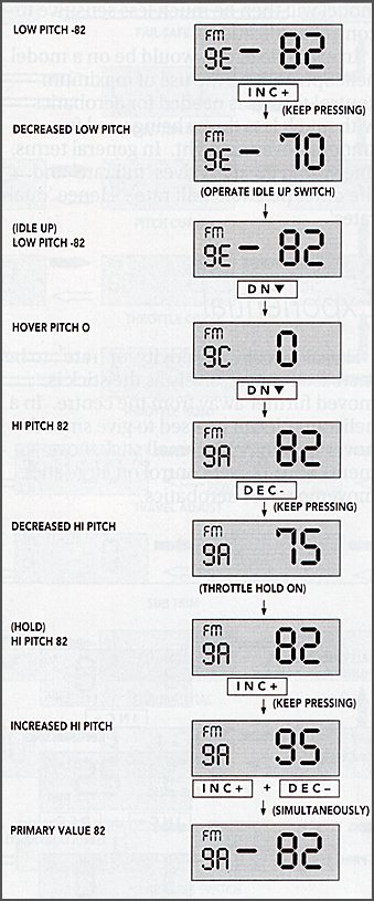
Here you can change the low, mid and high points of the pitch channel in exactly the same way as the throttle channel. Like the throttle, you can also set a different low pitch value when the idle up switch is in use. Three more figures can be set when the throttle hold switch is operated. This means that you can set a totally different pitch range for autorotations, if you wish.
You access this in exactly the same fashion as the throttle curve, with the display codes being 'FN9E', 'FN9C' and 'FN9A' for low, mid and high pitch points respectively. The default and maximum values are exactly the same as the throttle curve. Operation of the hold and idle up switches will automatically select the relevant values and allow them to be changed.
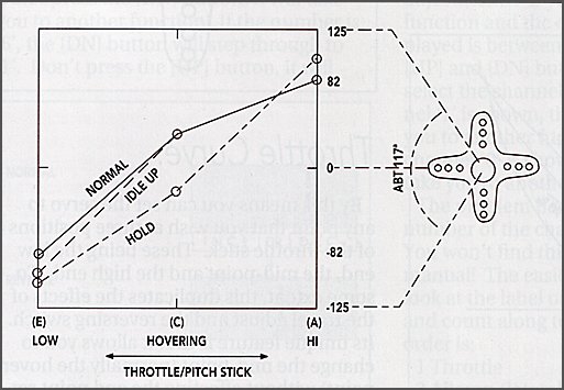
The throttle stick operates both the throttle and pitch channels simultaneously.
You can set the pitch and throttle values (servo position) for low, mid and high positions of the throttle stick.
Operation of the idle up switch allows you to set a different value for both pitch and throttle at the low position of the throttle stick. It also allows a different throttle value at the mid point.
Operation of the hold switch freezes the throttle at any desired position and allows you to set different pitch values at low, mid and high positions of the throttle stick.
Both the throttle and pitch 'curves' are expressed on the display in numerical form and this can be very confusing. This is made worse by the fact that most other adjustments are expressed as a percentage. One way around this is to use only the 'travel adjust' to make any changes, but you will not be taking full advantage of the equipments potential, nor will you be able to change the throttle and pitch at the mid point.
There is no 'right' or 'wrong' way here and you must decide what suits you best. Remember that the maximum range is from '-125' through '0' to '125' and the normal, or default, range is from '-82' through '0' to '82'.
So far we have concerned ourselves only with setting up each channel to our requirements. We now introduce a new concept called 'mixing'.
As we increase, or reduce, the pitch of the main rotor blades, they will need more, or less, power to maintain speed. This means that the tail rotor trim will change. To compensate for this we need to change the tail rotor pitch automatically as we change the main blade pitch. This is done by 'mixing' part of the pitch channel control signal into the tail rotor control signal. Both the amount and the direction of the mix must be correctly set.
Start in the usual way by pressing the [UP] and [DN] buttons together and then the [UP] button until the display shows 'CMIX' and a percentage (default 0%). This can be changed in the usual way by means of the [INC+] and [DEC-] buttons to a maximum of '-125%' or '125%'. You can set different values for climbs (up mix) and descents (down mix) by moving the throttle stick above or below the mid point. To establish the correct figures, it is necessary to fly the model and adjust the value until the tail trim does not show any marked change with sudden increases or decreases of throttle/pitch. To switch off this system move the throttle stick to each end and press both the [INC+] and [DEC-] buttons together to return the value to �0%'. Up and down mixes can be used, or switched off, independently.
In order to work in the correct direction, the value should be negative for helicopters having clockwise rotating main rotors (viewed from the top), and positive for machines with anticlockwise rotors.
Note that operation of the throttle hold will automatically switch off this function. The intention here is to avoid changes of pitch, during an autorotation, causing a corresponding change of tail trim.
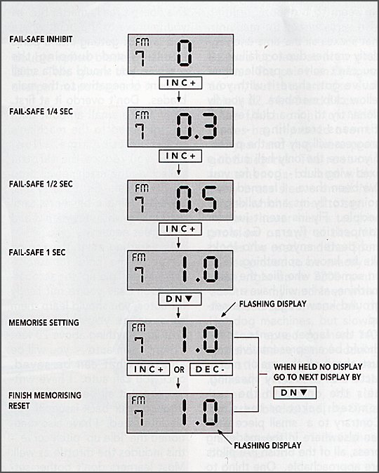
This function is only available when the transmitter is operating in PCM mode. Step through the functions until the display shows 'FN7'. If this is not available, check that the transmitter is not in FM mode (primary display shows 'F' instead of 'C'). The [INC+] and [DEC-] buttons will select the following options:
'0' If the receiver loses the transmitter signal, all controls will hold their positions until the signal is regained.
'0.3' If the receiver loses the transmitter signal, all controls will hold their positions for 0.25 seconds and then go to a preset position until the signal is regained.
'0.5' If the receiver loses the transmitter signal, all controls will hold their positions for 0.5 seconds and then go to a preset position until the signal is regained.
'1.0' If the receiver loses the transmitter signal, all controls will hold their positions for 1.0 second and then go to a preset position until the signal is regained.
To set the preset positions referred to above, first select the required time delay ('0' means that the controls will hold their last position) and then press the [DN] button. The time display will start flashing. Now hold the control sticks in the required position and press either the [INC+] or [DEC-] button. This stores the required positions in the memory.
No specific recommendation can be made as to which delay time to select. In situations where there is a lot of interference, a long delay (1.0) will tend to reduce the number of times that it effects the receiver. However, a second can be a very long time in some situations and a shorter delay may be preferable.
When the transmitter battery drops to about 9 volts, there will be a short audible alarm and the display will flash 'BAIT' continuously on all functions. When this happens, you must land the model immediately. This facility is completely automatic and requires no input on your part.
That concludes all of the adjustments involved in setting up the transmitter to suit a particular model. Remember that inputs are instantaneous; you don't need to do anything at all to enter them into the computer memory other than altering the value to what you want. You can fly the model between making changes and observe the result.
Way back at the beginning of this article, we mentioned the 'System Setting Mode' (press [UP] and [DN] and then switch on) and stated that 3 things could be done when this was selected.
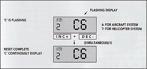
You can return all of the settings to the normal, or default, values, in one operation, if you wish. Select the display which shows 'FN2' and a flashing 'C' or 'F' and a solid '7'. If you now press [INC+] and [DEC-] buttons together, the 'C' or 'F' will stop flashing. This indicates that all of the settings have been returned to normal.
If the transmitter battery has been allowed to become completely discharged, or if it has been removed for more than about 3 minutes (including use with dry cells), the settings will become lost and the travel settings programmed into the transmitter may also be changed. When this does happen it will be indicated by the transmitter automatically going into 'System Setting Mode' when you switch it on. The display will show 'FN1 CH1 100' and the channel number will cycle through from '1' to '4'. Don't panic.
Hold both sticks in the full left and forward position and press the [INC+] button. Then hold both sticks in the full right and back position and again press the [INC+] button. All is now well. The values for each channel will now probably change from the '100' value as the display cycles through the channels. This is normal.
Yes, it does all look very intimidating at first glance, but you have nothing to lose by diving in and learning how to use it a little at a time. The 'Max 6' is actually a very basic set with only the bare minimum of functions needed to operate a modern helicopter. It is only the input system which is made rather involved in order to keep the cost within reasonable limits. There are vastly more complex helicopter sets available, some with even more convoluted entry systems and some with very simple 'user friendly' systems - at a price.
Nonetheless, they are all basically the same in concept and if you learn to understand one, the others will all seem simple.
Remember, you don't have to use the computer until you need it and understand what it is supposed to do. No matter what order you push the buttons, or how many times, you can't break it that way.
If you find it difficult to get the function you want, just keep pressing the [UP] button until it appears. The [DN] button will then find the channel that you want.
Once having overcome the hurdle of getting into the system, you can experiment and change the settings as often as you like. It won't wear out and the results are repeatable. This repeatability is the single most useful part of any programmable transmitter. Before computers came into use, any adjustments that were available depended on the setting of small trimmer dials which were far from repeatable.
If you become lost in your experimenting you can go through the system outlined above for returning all the settings to normal and simply start again.
Good luck and welcome to the club!

![]()
![]()
![]()
![]()
![]()
![]()
![]()