The kit - The motor and exhaust - Assembly - Main frames - Installation - Finishing off - Flying - Conclusions - Specification
After many years of writing kit reviews of helicopters, I have reached the point where it is difficult to get excited about the possibility of reviewing one more. Many of you out there will probably find this hard to believe, but it's not building the helicopter, it's the prospect of having to write about it afterwards and then have to take the complaints (usually not from the manufacturers) about what I might have said.
When the opportunity arose to review this machine it was not at all difficult to get excited about the prospect and I was sure that writing about it would not be a problem, particularly after seeing the kit. I was a little anxious about the fact that I might not like it, but that soon faded away when I realised the safisfacfion there was in just assembling it.
I remember some years ago when I was taken to task in an American magazine for saying that I had assembled a particular model in so many hours. For the record, the 'xl-pro' took me nearly a month of almost continuous spare time work. But then, I am older than Jim Davey.
This is undoubtedly one of the most sophisticated model helicopter kits available anywhere in the world. All of the control laakages are of the push-pull type, giving solid slopfree controls. The quality of the materials and the workmanship are first class. Having made several attempts to count the number of ballraces involved in the design and got a different answer each time, I can only say that there are around 80, plus 5 thrust races and a couple of one-way roller races. There are thrust races on main and tail blade holders and one on the mainshaft.
Many of the main components are in a carbon fibre (graphite) composite material. These include the upper and lower side frames, the servo mounts and radio tray, the tailboom and boom stays, the tail drive tube and the tail rotor blades, plus several small items. Most of the aluminium parts are anodised a gold colour and this contrasts nicely with the textured black of the carbon fibre parts to present a strikingly attractive appearance. A notable feature of the servo mount (servo side frame) is that it is insulated from the main assembly by rubber grommets
The canopy/cabin is a light flexible epoxy-glass moulding with an optional clear lexan window. If you decide not to use the window, there is virtually no trimming to be done. It is supported on three posts, via rubber grommets, making it easy to remove. Main blades are of conventional hardwood/balsa construction with bolt-on root reinforcements and three slots in each blade for the addition of the supplied lead rod. Self-adhesive covering material is also supplied.
Undercarriage is the well proven 'Tuf-Strut II' type. The radio tray is supported by two aluminium brackets which have cut-outs which can be used to mount the on/off switch and a gyro control box. These are inside the canopy, but it is possible to position the switch so that it can be operated without removlng the canopy.
Upgrades are continually being added to the kit and the review example included the latest double boom support and the latest clutch. The boom supports consist of a carbon fibre tube with a modffied ball link glued into each end. These snap onto balls bolted to the lower side frames and the tailplane mount.
The clutch and starter shaft are completely isolated from the motor and fan hub. Two tapered collets are used to attach the fan to the motor, one above and one below the fan hub. These collets have to be chosen to suit the specific motor being used and various types are available to suit any motor. The idea here is to give the correct alignment of the fan without any run-out, so that the use of a dial gauge is unnecessary.
The starter shaft runs in its own double bearing block and is supplied attached to the clutch and correcfly aligned. Correct alignment between the clutch and fan hub is by means of a rubber bush, which aligns the centre of the fan, and the actual drive is via two pins which engage between polyurethane rods in the fan hub. The total result here is that the fan hub and clutch are isolated and self-aligning.
It was decided to use an OS '61 SX-H' for the review and, following a 'phone conversation with Ted Schoonard, a Miniature Aircraft 'Nitro Pipe', as the exhaust system. The motor is specifically designed for helicopter use and features a ringed piston, with a steel liner and is intended to use fuel containing a moderate amount of nitromethane (10 - 30%). The exhaust is also intended for nitro fuels and is a stralght expansion chamber type (untuned).
An interesting rear attachment was supplied with this silencer (see photo). However, a slighfly simpler design based on one used with success on my pylon racers was utilised. This simply consists of a piece of silicon tubing around the outlet pipe with a bracket made from coathangar wire wrapped around it. The front of the silencer is joined to the header pipe with silicon tubing, which results in a floating muffler assembly, which is extremely quiet.
The alignment of the silencer outlet (facing rearwards and quite high) tended to deposit a fair amount of lubricant on the rear of the helicopter, so a commercial 45 degree angled ouflet extension was used and incorporated into the rear support bracket. This probably loses quite a bit of power, but the model stays clean!
As the motor does not form a direct part of this review, it will be dealt with elsewhere.
This follows the well established method whereby numbered bags of components match numbered sections in the assembly manual. However, Miniature Aircraft have added a few ideas of their own. One is that the manual starts with a full list of each main assembly and sub-assembly - rather like a contents list. This certainly makes things much easier to find when you need to repair or maintain something.
Another useful idea is that each numbered bag has a plastic tube which contains all the smaller items, nuts, bolts, etc. heat sealed in compartments. One end is labelled 'A', which signifies that you open that one first. As you work along the tube, opening each compartment in turn, you are fed the items in small amounts as you need them. This means that you don't have to go looking for a particular bag, or things which might be in other bags and you don't get confused by having too many items to sort through at one time.
Let's pause here and talk about the manual. This is just about the best I have seen. It starts off by telling you about the dangers of helicopter operation and gives guidelines for safe operation. It then goes on to tell you what you need to complete the model and follows up with a comprehensive list of tools. both essential and optional. Then comes that list of assembly sections. Only then do you come to the actual instructions which detail everything, right down to the last detail.
This fine attention to detail is really essential because, make no mistake, there is a lot of work in this helicopter and it deserves your full attention. This big investment in time and energy is, however, amply repaid in terms of satisfaction when you survey the finished article.
Full details are given regarding servo arm lengths, pushrod lengths and final alignment. If followed closely, these are all close to the optimum. This is followed by a list of all the items you will need to operate the model, notes on starting and stopping the engine, first flight adjustments and final trimming and tracking. Finally, there is a page giving full size drawings of all the fasteners involved. Very impressive.
The kit includes allen keys and loctite, and only a few other tools are requlred for completion. It would be pointless to go through the entire assembly step by step, especially as the manual does this far better than I could. However, the salient points will be briefly covered for the sake of the potential purchaser.
When I started, I did not have either the motor, or the servos to be used, available. For this reason, I departed slightly from the suggested order of assembly, but this caused no problems. In fact, I started with the tall rotor gearbox and went on to complete the whole rear end, including the boom and tail drive. This drive consists of a carbon fibre tube which is supported by two ball races which are located within the boom by '0' rings. A 'ball and pin' coupling is attached to each end of the drive tube, and these locate in delrin couplings on the tail gearbox input shaft and the tail drive take-off shaft. This means that there is a very positive drive, but which allows the boom to be easily removed, if required.
The main frame assembly consists of upper and lower frames, with the upper side frames being more closely spaced than the lower frames. Motor, tank, undercarriage and radio tray are all mounted to the lower side frames, while the clutch, mainshaft and main gear, tail take-off drive, collective and elevator push-pull assemblies, tailboom clamps and the gyro are all mounted on the top frames. One very big advantage of this system, as I soon discovered (see below), is that you can split the upper and lower frame assemblies for repair, or maintenance, without any need to disturb the motor/clutch alignment.
The correct installation of the clutch is quite critical. It is essential that there is some vertical play in the clutch bell and pinion. A special shim is provided to set the clearance between the clutch and the fan hub (remember there is no direct connection between them). Initially, I set things with no play in the clutch bell and the clutch shaft tightened up when I first ran the motor. Re-reading the instructions and resetting sorted that one out.
A conventional autorotation freewheel is incorporated within the main gear hub. This is supplemented by a unique 'slipper clutch', below the gear, which allows an adjustable amount of friction to be applied between the gear and the shaft. The idea here is that there is a 'soft' drive to the taifrotor during autorotation. Properly adjusted, this allows you to steer the tail without putting too much drag on the main rotor.
The cyclic and collective pitch systems are interesting (I almost said 'fascinating'). In Europe, the system used would be called 'mechanical CCPM', which simply means that the swashplate moves up and down for collective inputs and that this is mechanically mixed with the cvclic controls. Just how this is done on the 'xl-pro' is ingenious, very smooth in operation, totally solid and free from any form of interaction.
With the exception of the throttle servo, all servos have two pushrods to give the aforementioned 'push-pull' control. The tailrotor and collective servos both drive bellcranks (fully ballraced), which then drive their respective controls - the collective via a doubled-up pushrod. These bellcranks equalise the loading on the servo output shaft and increase their life. In the case of the fore/aft cyclic control, the two pushrods go to a larger bellcrank which also serves the function of removing any interaction when collective is operated.
The lateral cyclic servo has two pushrods which each drive a bellcrank on each side of the upper frames. These bellcranks (again fully ballraced) then drive pushrods which go up to the swashplate. Those of you who have been paying attention will be wondering what happens when the swashplate moves up or down. This is taken care of by allowing the servo to rock back and forth.
The swashplate mixer/washout unit has no less than eight ballraces which, in combination with countless ball-races in the pitch system, means that the whole assembly will fall under its own weight. In fact, one slightly tight ball-link will stick out like a sore thumb.
Assembly of the rotor head and blades requires you to make some decisions. Each flybar paddle is built up from three mouldings and some lead weights. Advice is given as to the amount of weight that you might require, depending on your flying style. I ended up with a paddle weight of 35 grams. The design of the paddles makes sure that the weights are firmly secured. The plastic part of the paddles is threaded onto the flybar in the usual manner. However, the flybar also goes through metal inserts in the paddle with grub screws which lock the paddle firmly in position. You also have to decide on the mIxing ratio used on the blade holder mIxing arms, although :this can easily be changed later. I set things at 1:1 to start with.
Finally, you have to decide on the weight of your main blades. Here again, advice is given on just how much lead to add dependent on your flying requirements. I added all the lead and ended up with a blade weight of 217 grams. The blade roots have plastic cuffs, with carbon reinforcements, which are glued and bolted to the blade. Specific instructions are given that the glue must be slow cyano ('Slo- Zap'). I am allergic to Zap, but went out and bought some anyway!
Apart from the lateral cyclic servo, all of the servos are mounted on a double frame (of carbon fibre), which is isolated from the rest of the machine by rubber grommets. Small blocks of ABS material are supplied to receive the screws which secure the servos. These are first glued to the frames and then secured by small countersunk screws. It is suggested that you use a drill press with a travel limiter to drill the holes for this (Dave Wilshere went out and bought one especially for this job!), but I managed quite well with a hand drill.
This is described in such complete detail that the only decision that you have to make is just where the wiring should go. Actually, you do have some choice regarding the switch location and the disposition of the gyro depends to some extent on the type used. The recommended type is the Japanese JMW unit. By coincidence, I had one of these units which I had never used.
There is a custom designed location for the actual gyro immediately behind the mainshaft at the top of the upper side frames. In my case, the wiring between the gyro and its separate electronics box was just long enough to allow the electronics to be mounted under the receiver as suggested. I shortened the cable between the electronics package and the control box in order to eliminate as much spare wiring as possible. The JMW can be used with a separate battery if required and a shorting plug is supplied when using one common battery. I removed this too and relocated the shorting wire inside, on the PC board.
I also shortened the servos leads and rewired the switch harness in order to remove excess wiring. The battery location needed some thoughL The instructions advised that it might be necessary to locate the battery behind the tank in order to achieve the correct CG location. I was using one of the new smaller 1200 mAH packs, so I tried this, but found that even with the tank empty the CG was behind the mainshaft. The optional suggestion was to locate it vertically in front of the servo mounts. However, I found that mounting it under the radio tray and as far back as possible, while avoiding the switch and gyro control box, gave a CG position just in front of the shaft when the tank was full.
Incidentally, I check the CG position by the Dave Wushere method. This entails holding the rotor head with the machine on its side and letting the model rotate around the mainshaft. This is the only method which does not need some sort of interpretation and is uncritical of the way that the model is supported.
I have noticed that most 'x'-pro' builders seem to use what I would describe as a 'soft' colour scheme, i.e. no hard trim lines. After some thought I realised that the shape of the cabin/canopy encourages this. The shape itself is very soft and it would seem quite out of place to use a colour scheme which had sharp edges. This worked quite well with my natural laziness (no masking) and I decided to follow suit! 'Dupli-color' works well, both on the cabin and the stabilisers.
The large tank is housed in cut-outs at the rear of the lower side frames. Here again, the innards of the tank are specifically detailed - but there is no mention of the external pipework. This actually worked to my advantage because, if the instructions had said to fit a filter, I would have fitted one! My personal opinion is that filters are an accident waiting for a place to happen.
If you are already using a starter extension shaft, it may require a slight modification. The 'x'-pro' uses a novel form of starter connection which MA call a 'Uni-lock' connector. This is a ball-and-cup universal joint; the ball going into the end of the starter extension and the cup being fitted to the top of the clutch shaft.
In finished form, with an OS '61 SX-H', a Miniature Aircraft 'Nitro Pipe', four Futaba '9201' servos, a JR '517' servo, a JMW gyro, a JR 'PCM 10' receiver and a 1200 mAH battery pack, the machine weighed exacily 9 pounds (4.09 Kg) without the main blades fitted. With the kit blades, this brought the total weight to 9 pounds 15 ounces (4.51 Kg).
Running up the model showed that the blades were in track. Subsequent flying, and checking the static tracking, showed absolutely no need for any adjustment whatever. Lifting off into a sliglifly rich hover showed that it was actually in trim, with the throttle/collective stick in the middle too! This was too good to be true.
Now, just where did I make my first mistake. For the first couple of tanks I intended to use Model Technics running-in fuel, which is called 'Long Life'. It has 25% castor oil and only 3% nitro. The plug used was the one which came with the engine, an OS number '8'. Using this fuel and running on the rich side, the motor would occasionally stop - dead. There was no problem with idle, or transition. The stops would occur when running at constant speed and were clearly due to the 'fire' going out. There was plenty of blade inertia and I simply landed the model when this occurred.
With a new plug, the review photos still not taken and in breezy conditions, I started to explore the forward flight characteristics. This came to a sudden halt when the motor stopped again in fast forward flight at low level - and downwind! I had already done an autorotation from reasonable height and the set-up was correct for this. The snag was that I couldn't kill the forward speed. The model hit hard and level, bounced back to about ten feet and turned over.
It took all of this unbelievably well. The blades were not broken, but the boom and drive tube were wrecked, the blade feathering spindle bent and the flybar 'S' shaped. The undercarriage was unscathed ('Tuf-Strut' indeed) and the mainshaft only bent about 10 thou. Apart from a stripped gear in the lateral cyclic servo, there was no radio damage.
With me rather chastened, it was soon back in the air with the aid of spare parts supplied by Modtec, together with 'Supagio 16%' fuel and an Fnya '3' plug. It hasn't missed a beat since! The incredible thing is that it is still in-track and in-trim, which speaks volumes for both the design of the machine and the setting-up instructions.
The design and execution of this very complex machine are first-class, complemented by an excellent instruction manual. Carefully built, it will repay the effort with a smooth, quiet, machine with staggering performance potential. Apart from an early crash, which was almost certainly my fault, I have never felt so happy with a new machine so early in its life. It still seems incredible that the machine was so near to optimum hovering trim without any adjustment. It was never my intention to test the strength and repairability at such an early date, but that too proved to be impressive.
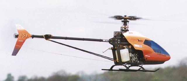
At the time of writing, it is difficult to find any sort of decent weather and I am becoming impatient to get on with exploring the models potential in reasonable conditions. taking the flying shots which accompany this article was done in very cold, turbulent conditions which increased my respect for the model.
No one will ever take me seriously unless I criticise something. OK, don't take me seriously!
| Name | X-Cell 'Xl-pro' |
| Main rotor diameter | 60 in (1.70m) |
| Overall length | 55 in (1.56m) |
| All-up weight (dry) | 9lb 15oz (4.5Kg) |
| Main gear ratio | 9.5:1 (9:1, 9.4:1, 9.6:1 optional) |
| Main to tail gear ratio | 4.66:1 (4.33:1, 5.2:1, 5.6:1 optional) |
| Control requirements | 5 servos and a gyro |
| Power requirements | '61' engine |
| Manufacturer | Miniature Aircraft USA, 3743 Silver Star Road, Orlando, FL 32808, USA. Tel: (407) 292-4267. FAX: (407) 292-4296. |

![]()
![]()
![]()
![]()
![]()
![]()
![]()