The kit - Assembly - Installation - Flying - Conclusions
Dieter Schluter is rightly regarded as the father of the modern R/C model helicopter and his own company has been producing kits for some twenty years or so. These have usually been at the forefront of design and development and have many competition successes.
Herr Schluter recently retired and control of the company has now passed to the Robbe concern, which continues to produce updated versions of many of the kits. Shortly before his retirement, Dieter announced the new 'System 88' which was incorporated into the 'Junior 50' and 'Scout 60' models. This is a moving swashplate control system which utilises mechanical mixing.
A full description of how this works lies outside the scope of this review and will be covered elsewhere. Briefly, three servos (pitch, aileron and elevator) are fixed to rocking mounts and move together under the control of the pitch servo. This raises and lowers the swashplate for collective pitch control. The aileron and elevator servos each drive two bellcranks (four in all) which have links to four equally spaced points around the swashplate.
These points are not - as you might suppose - at each side and fore and aft, but are at 45 degrees to the models centreline. The resulting control inputs are thus 45 degrees behind the usual input, but this is taken care of in the rotor head geometry. This actually produces a simpler linkage in the head itself, with all control rods being straight and direct. There is, of course, a price to pay for this, in that the complication has been moved from the rotor head to the servo area.
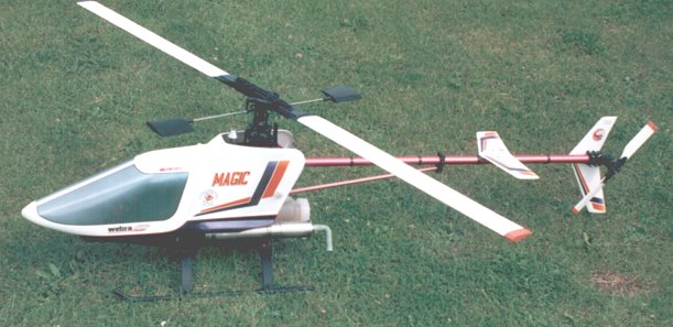
The very latest Robbe/Schluter offering is the 'Magic' which also uses the 'System 88' control system. At first sight, the model has a superficial resemblance to the 'Scout 60', but is in fact a completely new - and larger - model with many new features. These include a completely new drive train, a modified tail gearbox, a spring loaded starter shaft and a brass tube in the tailboom for the tail drive shaft. The usual woodwork associated with the servo mountings is replaced by easily assembled plastic mouldings.
Just how many of these are of Schluter origin and how many are Robbe, we shall never know - but I have my suspicions!
This is supplied in two boxes, one containing the mechanics and another the cabin mouldings. In common with just about every other model helicopter kit on the market, the various sub-assemblies are in numbered bags which correspond to numbered sections in the instructions and on the drawings. It was rather disappointing in this case to find that all of the bags were just piled loosely into the main box, with no attempt to separate them.
Two large double sided sheets of drawings are supplied which cover all of the assembly very clearly, with each part and sketch being identified by number. These are backed up with separate detailed instructions in several languages and which again refer to the sub-assembly number. This approach is essential for any item which is intended to be sold in the European marketplace, but one misses the Japanese/American approach of separate stage by stage sketches with integral instructions. Curiously, despite the fact that a gauge is supplied for setting up the various linkages, there is no information whatever on setting up the control throws and no recommendation for rotor RPM.
The main structure consists of the familiar two side plates, but these are only three-quarters of an inch apart. This a characteristic of all Schluter kits, not just the 'Magic'. A substantial internal frame accommodates the various bearings for the drive train. At the rear, an aluminium bracket serves the dual purpose of tank mount and undercarriage brace. Despite this, all of the load on the plastic undercarriage struts has to be absorbed through the two narrow areas in contact with the frame.
Another common item in Schluter kits is a front bulkhead which serves to locate the cabin. On the 'Magic', this is screwed to the rear of the plastic servo mounts. Actual location of the mounts to the main frame is by two small lugs which fit between the side plates. The result is far from rigid and is aggravated by the fact the frames are cut away to a narrow strip at this point to save weight.
Tailboom location is by two plastic mouldings clamped between the side plates. The mouldings incorporate lugs which are a very snug fit into cutouts in the plates and this effectively prevents any up or down movement of the boom. Two mouldings fit around the rear of the boom and provide a mounting for the fin and the new tail gearbox. Previous boxes included a spigot which fitted into the boom and which made fitting into a fuselage a difficult operation. The new casing has a front flange mounting.
Unlike many modern kits, the whole of the rotor head has to be assembled by the builder. The head design is the now familiar system having a through shaft acting as a blade axle, with rubber 'O' rings between the shaft and the rotor head. Each blade holder has two axial bearings and a thrust race.
Three sets of flybar paddles are supplied. Two of these are simple thin plastic mouldings in two different lengths. The third set are a new design which are much thicker and hollow which makes them fairly light. One set is intended to be fitted to a threaded rod through a tailboom bracket and to serve as a tailplane. While the instructions state that the shortest paddles should be used for this purpose, it is common practice to fit the shorter set to the flybar and use the longer set as the horizontal stabiliser.
Main rotor blades are the familiar hardwood/balsa composite and are fairly heavy at around 6 ounces. Covering supplied is a white self adhesive plastic material.
Some thought went into the matter of which motor to use for the model. A conversation with Jack Williams revealed the information that the only motor which would readily fit was the custom-made Schluter/Webra 61. So one was ordered, with the matching silencer.
I had forgotten that this motor was available in both ringed and ABC form, so did not specify which one I would prefer. The motor duly arrived in ABC form - which is not what I would have specified, since I have long believed that this was not the ideal set-up for helicopters. In fact, it has proved to be most impressive so far - but I have had to buy a new starter and battery to turn the brute!
Later information reveals that other motors will fit, but you will probably need the aircraft version rather than the helicopter type. By now, Jack should have the necessary adapters for any motor, anyway.
This presents no real problems until you get to setting up the clutch and gear train. The clutch is another new departure for this manufacturer and is best described as 'Heim type'. It sits between the cooling fan and the motor and has two ballraces which fit on to a plain section of the motors crankshaft. Since the fan fits on to the shaft after the clutch and is secured by the usual tapered collet; this collet has to be tightened onto the clutch - which is facilitated by a spacer between the clutch ballraces. Despite dismantling the assembly several times and resiting the ball races within the clutch, the unit refuses to spin freely. It has still not loosened up after several hours flying.
The gear train is in two stages and could also be said to be similar to that used in Heim models. Drive from the clutch pinion goes via a short shaft to an internal pinion which drives on the inside of the main gear. Alignment of the first drive shaft and the main shaft is fixed, by means of a sub-frame bolted between the side plates. This would appear to be a little on the tight side and the result is a lot of gear noise.
As the motor is rather wider than the main frame, the engine mounts are machined blocks which bolt onto the outside of the frame. The only adjustment of the mesh between the clutch pinion and the first stage gear is via a small amount of play in the blocks fixing holes. After the first heavy landing had completely upset the mesh I found it easier the lock the blocks in place with a small amount of cyano and adjust the mesh by shimmimg between the motor and the blocks.
At the other end of the train the tail drive is taken from a fairly conventional bevel drive from the top of the main gear. This is, in fact, separate from the gear itself, to accommodate an optional system to drive the tail rotor during autorotation. Here again, there is no facility to adjust the mesh in a satisfactory manner. Although the fixing holes for the tail pinion bearing block are slotted, the actual position of the tail boom is a little on the low side, which means that the natural position for the pinion is also too low. Raising the bearing block to its upper limit means that there is still a very tight mesh. The holes could be stretched a little, but the actual mesh is already poor due to the tail drive wire being bent upwards to accommodate the raised pinion position. Possibly, the answer here is to fit a thinner washer under the main gear, or even modify the spacer between the main gear and the tail drive gear.
It has been common practice to fit a tube into the tail boom to accommodate the tail drive shaft. On the 'Magic', the fact that this is already provided actually makes the mesh of the tail drive gear more critical. Most other European manufacturers now use a tube with a plastic (usually teflon) liner in the tube.
The result of all of this is a gear train which is tight and noisy. Another result is the incredible depth of the overall unit. Those readers who remember the Schluter 'SX81' may recall that the idea was to reduce the overall height of the mechanism. One is inclined to wonder whether the designer had a change of heart, or the management changed the designer!
One very nice feature of the new tail gearbox is that the grubscrews securing the gears to the shaft are accessible from outside the box via holes in the casing. These holes are then blocked off by other grubscrews to make the box grease tight. However, the gears are held by a single grubscrew with no corresponding flat on the shaft and no instruction to make such a flat. Needless to say, I added flats to the shafts in the appropriate position. Nonetheless, a single grubscrew falls far short of the sort of engineering we expect these days. The tail drive wire does have flats ground on each end, but, here again, it would be nice to see more than one grubscrew.
I have already described elsewhere my problems in painting the canopy. It is essential that the mating flanges of the two halves are sanded before attempting to glue them together. Cyano then works very well. If you wish to tint the canopy on the inside, this should be done before joining and you must modify the front bulkhead, or the servo mounting frame, to avoid an unsightly mark appearing where the top right corner of this touches the inside of the canopy.
It is not at all clear whether the front underside of the canopy should be removed after joining or simply separated to assist in fitting it to the model. I decided to remove this, which results in a convenient position to mount the switch and charging socket on the underside of the lower servo frame. There is also room here for a mixture servo, if required.
The standard silencer and fitting kit works well. It is very quiet and obviously efficient. However, the position and angle of the outlet is such that the whole model rapidly becomes plastered with unburnt exhaust goo. By far the dirtiest running model I possess. You win some, you lose some...
No problems were experienced with the assembly of the rocking servo mounts, once the servos themselves had been attached to the plastic mouldings. No screws are supplied for the servos and it is necessary to find some suitable self tapping screws, since the usual woodscrew type supplied by most radio manufacturers is not really suitable for the plastic mounts
As already noted, a gauge is supplied which positions the swashplate at a nominal neutral point so that the servo linkages can be set with the servos also at neutral. As the 45 degree input to the swashplate can be a little confusing, the easiest way to visualise the working of the system is to position the flybar at right angles to the boom - which will then give normal flybar action for elevator inputs; or parallel to the boom - which gives normal action for aileron inputs.
Having said earlier that there was no information on control throws, there is a recommendation for the servo arm lengths, but this refers to Robbe servos. Having decided that this would make a good starting point, I found that it gave an incredible amount of flybar movement - approaching 30-40 degrees in each direction - so cut the movement down. Subsequent flight tests showed that all of this movement was, in fact, required for normal control.
The full complement fitted to the review model consisted of 5 JR 4031 servos, plus a 505 servo for mixture control, a PCM 10 receiver, a 1200 mAH battery pack and a Quest gyro. In this form, final flying weight with the wooden blades supplied came to 10.5 pounds.
Since there is no way of fitting a propeller to the motor used, it was not possible to bench run it before fitting it in the model. Having no previous experience of Webra motors, a bench run would have been useful to become familiar with it. Therefore, I used my usual system of removing the complete rotor head from the model and running a tank of fuel through the motor in a low load condition - being careful not to use to much throttle opening.
It soon became apparent that removing - or at least, loosening - of the plug was essential to stand any chance of turning the motor at a decent speed. A new starter and battery has not really helped the situation much! Once running, however, the motor proved to be easy to adjust and simply does not want to stop. Contrary to what you may have read elsewhere, ABC motors need a lot of running in and the unit is still improving.
Having replaced the head and checked the tracking, the first lift-off was uneventful but there was a distinct lack of cyclic response, so back went all that movement that I had removed earlier. At this stage it began to become rather apparent that the tail was very lacking in power. At first, this appeared as a very marked tendency to swing to the left on lift-off. No amount of fiddling with the ATS system could fully remove this and the penny dropped when I attempted to turn right - it wouldn't!
Investigation here revealed the startling fact that the main rotor to tail rotor ratio was only 3 to 1! Most models have around 4.5! There is a modification kit available which changes the tail gearbox ratio to 1 to 1, thus speeding up the tail, but this will still give an overall ratio of only 3.88. The instructions contain a warning not to confuse the tail gears, since if these are wrongly assembled the tail will turn 'too fast'. In fact this would give a ratio of around 5 to 1. Hmmm...
It is my intention to try the modified tail box ratio in the future and I will report further.
So, on to some more flying. Despite a very spritely climbing performance, it does not seem to want to loop in a very tidy manner. There simply is not enough 'steam' to go cleanly over the top and it 'mushes' on the pull-out. In fact, early loops were tried without the nose fairing and were somewhat better, which suggests that it is nose heavy. A very marked tendency to fall out of rolls in the inverted stage suggests the same thing, although the model does balance as suggested. Using more negative does not help the rolls very much; the only answer seems to be to apply forward stick during the inverted - which kills the forward speed!
Stability in fast forward flight is not what we have come to expect these days and there is a tendency to porpoise and to zoom unexpectedly at speed. The model has yet to be flown in very windy conditions, however, which will be the real test.
Autorotations are quite good on the standard wooden blades, but the model tends to 'nod' on the way down, which suggests that heavier blades - or a higher blade speed - is needed. Actually, it shows a distinct inclination to nod at other times, so perhaps I am not running enough head speed - something which I have never been accused of! Overall, the performance is rather disappointing and one cannot help but feel that the complex, and far from compact, mechanics have a lot to do with that.
Five years or so ago, this just might have been hailed as the best thing around. By todays standards, it is heavy, mechanically noisy, complex and messy. Anyone who wishes to use the model for serious competition use would do well to investigate using the far more rigid 'Scout 60' woodwork in place of the plastic servo mounting structure, and some change to the tail ratio is essential.
Hopefully, the use of GRP blades will improve matters somewhat and I also intend to fit a bigger tailplane, since I have my doubts about the usefulness of those two small paddles.
