 Back to Hornet index.
Hornet hints
Construction hints - Operating tips - Modifications and improvements
Check that the main shaft is vertical and that the undercarriage skids are parallel in plan view before finally gluing the undercarriage in position.
 Check three times before applying the smallest amount of cyano. Check again before adding any more.
Run the motor in for several hours on a low voltage. This should be pure DC to reduce any sparking at the brushes. Model train controllers are sometimes suddested, but are not recommended. They are usually low frequency type controllers (typically mains frequency) which can reduce the strength of the motors magnets.
Remove material from the inside faces of the head pivot support as necessary to get the head to pivot freely.
Only glue the tail boom in the chassis at the support saddle adjacent to the main shaft lower bearing. Better yet, fix the boom with a small grubscrew. The screw can cut its own thread in the plastic of the chassis. The same can be done at the tail gearbox, though this is more tricky.
Make a new pin to attach the main gear to the shaft which is longer so you can get a grip on it when necessary. Use a straight pin to line things up before fitting.
Pack up both cyclic servos as required. Ensure that the servos cannot move during operation. If necessary use a small cable tie around the servo and mounting plate.
Tint the canopy before you start cutting.
Glue the tail servo support plate to the left side of the boom, not the right as shown in the manual. Another alternative is to glue the plate above the boom with the servo laying down.
Add heatshrink tubing at both ends of the tail pushrod so that it is a good fit in the end fittings.
Use a simple training gear for your first flights and find somewhere with some room!
The antirotation link above the swashplate needs to be very securely glued in place. If it comes adrift the model will be unflyable. I've been caught out twice by this. Once is carelessness, twice looks like a conspiracy.
The boss on top of the main gear is slightly larger than the inner diameter of the outer part of the lower main shaft bearing. If your model squeaks, the solution is simple. Put a slight chamfer on the outer edge of the boss on top of the gear. Most machines will need some form of spacer here to avoid loading up the tail drive to some degree. It needs to be very thin and it is difficult to see whether you have it right.
John Kallas' website has an easy way of increasing the head stiffness which is well worth trying.
It is fairly important that the response to cyclic inputs (fore/aft and lateral) are similar. The above stiffener does help to show up any differences here. When they are balanced the model is much more comfortable to fly.
Check three times before applying the smallest amount of cyano. Check again before adding any more.
Run the motor in for several hours on a low voltage. This should be pure DC to reduce any sparking at the brushes. Model train controllers are sometimes suddested, but are not recommended. They are usually low frequency type controllers (typically mains frequency) which can reduce the strength of the motors magnets.
Remove material from the inside faces of the head pivot support as necessary to get the head to pivot freely.
Only glue the tail boom in the chassis at the support saddle adjacent to the main shaft lower bearing. Better yet, fix the boom with a small grubscrew. The screw can cut its own thread in the plastic of the chassis. The same can be done at the tail gearbox, though this is more tricky.
Make a new pin to attach the main gear to the shaft which is longer so you can get a grip on it when necessary. Use a straight pin to line things up before fitting.
Pack up both cyclic servos as required. Ensure that the servos cannot move during operation. If necessary use a small cable tie around the servo and mounting plate.
Tint the canopy before you start cutting.
Glue the tail servo support plate to the left side of the boom, not the right as shown in the manual. Another alternative is to glue the plate above the boom with the servo laying down.
Add heatshrink tubing at both ends of the tail pushrod so that it is a good fit in the end fittings.
Use a simple training gear for your first flights and find somewhere with some room!
The antirotation link above the swashplate needs to be very securely glued in place. If it comes adrift the model will be unflyable. I've been caught out twice by this. Once is carelessness, twice looks like a conspiracy.
The boss on top of the main gear is slightly larger than the inner diameter of the outer part of the lower main shaft bearing. If your model squeaks, the solution is simple. Put a slight chamfer on the outer edge of the boss on top of the gear. Most machines will need some form of spacer here to avoid loading up the tail drive to some degree. It needs to be very thin and it is difficult to see whether you have it right.
John Kallas' website has an easy way of increasing the head stiffness which is well worth trying.
It is fairly important that the response to cyclic inputs (fore/aft and lateral) are similar. The above stiffener does help to show up any differences here. When they are balanced the model is much more comfortable to fly.
 |
If you are used to collective pitch IC helis and find that the response is too slow, one improvement is to reduce the free teeter movement. The easy way is to add spacers each side of the boss on the head pivot support so as to limit the movement.
Don't be surprised if this gives an improvement in flying time. |
I know that others have tried damping the teeter by means of a piece of wire bearing down on the blade fixing bolts. However, that still leaves you with, effectively, two teeters, including the flexibility in the head. There's another potential problem with that method in that the blade bolts swing from side to side when the flybar teeters and the wire could seriously impede the control.
The packers need to be fairly hard, so they do not become crushed. PCB material. 0.030" thick is about right. This gives about 3/8" movement at the blade tips.
Another alternative is to use pieces of carbon rod, or wire, glued below the head.
My carbon shaft eventually cracked on the fifty third flight and caused a bad crash.
Here's my solution to both that and the antirotation link.
Obtain some K&S brass tube, which is labelled as 2.5mm diameter (that's the bore). Chuck a piece in a minidrill and polish with fine wet and dry paper until it is a snug fit in the bearings. Add a 1mm diameter hole at each end and you have your new metal shaft.
A small neat soldered joint is as light as anything else and a lot more secure! Solder two pieces of 1/32" piano wire to the shaft to make a double A/R link. The standard link simply pushes one of the swash links around so that the swashplate follows the head. If the swashplate gets ahead of the link, it reduces both the control deflection and the power and the compression will make the swashplate tend to stay ahead rather than righting itself. This system traps both links fore and aft. The easy way is to notch the shaft each side and solder a 'U' shaped piece of wire in the notches, adding a single turn of 5 amp fuse wire first. Cut off the 'U' and trim to length.
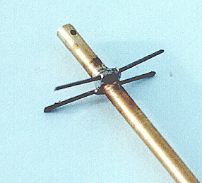
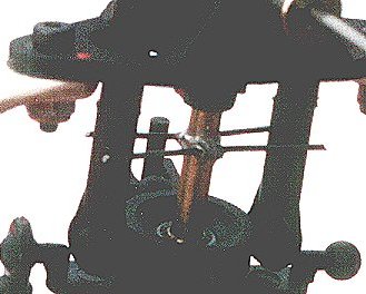
Modified antirotation link.
The complete item weighs around 5 grams. It may be an overkill, but you can forget two big problems.
This shaft will survive most normal knocks without bending. If it does become bent, it is a simple matter to replace it.
The actual movement of the swashplate is severely limited by the way it fits on the shaft and careful adjustment of the ATV is needed to avoid overdriving the servos. Small wonder that many people are using reverse exponential (that's positive expo to Futaba users). Unfortunately, my brain is linear and I could see no advantage in going down that route.
Chris Rigoleth makes a swashplate ball modification, which allows you to get more swash movement and gives much better location.
With 3/8" of free teeter and as much travel as the swashplate can accept, I have a set-up that I am comfortable with.
The flybar teeter (E045) is very badly supported by the two 3mm x 3mm grubscrews. This causes rapid wear on the bearings and increases the load on the pivot support (E044). John Kallas can supply an aluminium pivot support and things can be improved by changing the grubscrews to 4 or 5mm long ones. Screw them in until they just touch the flybar and back them out half a turn.
The method of supporting the battery is very fiddly. I originally discarded the small plastic hooks which hang from the longitudinal struts between the U/C legs and simply hooked small rubber bands around those struts and around the battery.
I now loop the bands around the struts and through themselves so that they are permanently attached to the struts alongside the motor. A piece of 1.5mm carbon rod is mounted above the struts using miniature bands cut from silicon fuel tubing. This can be pulled back to make it easier to attach the rubber bands to the ends after passing over the battery. Finally, this rod can then be pushed forwards to snug the battery up against the motor.
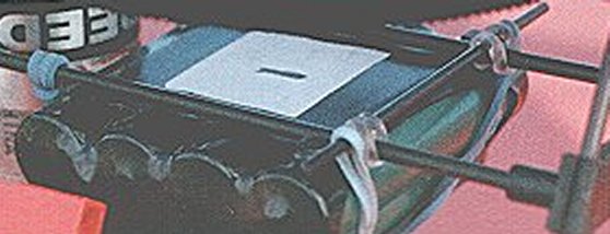
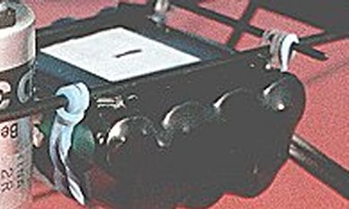
I attach pads of plastic card above the battery to locate against those longitudinal struts, so that the battery cannot move sideways and escape in a hard landing. By suitably locating four small squares at the corners of the battery it is possible to mount it with the cells lengthwise or crosswise. A piece of foam rubber can be mounted on the rear of the motor to adjust the battery position if needed.The bands should be crossed over below the battery to further discourage it from escaping.
This page will be frequently up-dated
Other Hornet pages on this site: