I mentioned that I had stripped the original tail input gear due to the shaft moving downwards in a hard landing. This gear is the same as the motor pinion. Replacements come in packs of two or four. I got two, but may possibly regret not getting four! The new ones are black, rather than the white of the originals.
I had hoped to be able to replace the gear without dismantling the model, but my earlier boom repair meant that I could not slide the tail drive out from the rear of the boom. I was glad here that I had only glued the boom to the support saddle. Having got things back together, I looked very carefully at the alignment of the new gear and the main gear. This, like the motor pinion is very difficult to judge because they are hidden when installed. You can feel when there is slight play in the motor pinion, but the tail drive is more difficult. Incidentally, I did originally have to elongate the holes for mounting the motor so that it was nearer to the main gear in order to get a good mesh with the motor pinion.
I feel that some sort of spacer may be needed above the main gear to get proper mesh with the tail drive, but I left things alone for now.
Having given my two batteries a couple of trickle charges (70mA for 16 hours) I decided to treat them differently to see if this produced any useful information. I continued to trickle charge one battery while using the supplied MS fast charger for the other. A check on the charge rate showed it to be 760mA. The first few charges resulted in the battery getting quite hot. Because of this, I terminated the charge at one hour. After a few more charges, the battery got rather less warm and I allowed the charger to cutoff, which occurred after around 65 - 70 minutes.
The trickle charged battery gave flights of around seven and a half minutes to the cut off point of the speed controller with a long dump. Typically, the model would land 15 - 20 seconds before the ESC cut off.
The fast charged battery gave flights of around 8 minutes to cut off, with the model still skating around in low ground effect when this occured.
After six cycles, the battery which had only been trickle charged was now fast charged. This gave the longest flight so far at 8 minutes 12 seconds to cut off. The model was still flying (just) when this happened.
Slow charging the battery which had been fast charged (are you still with me?) gave 7 minutes 55 seconds to cut off, but the model was solidly grounded at 7 minutes 25 seconds.
So, it's fast charge from now on, but I will still give an occasional trickle charge.
With the model in trim and flying regularly, my main problem lay in a certain vagueness in the cyclic response which made it difficult to hover in one spot. I usually found myself in a situation where the model was moving backwards and forwards in a pendulum motion. Occasionally, it would do this from side to side. The effect was rather like having a slow servo.
I experimented with moving the flybar weights in and out on the flybar. Things were definitely better with the weights in the inner position. This meant that I could apply any necessary correction quicker and avoid the situation developing. Increasing the cyclic throw also helped, provided I did not let the oscillation build up too far. When this happened the tendency was to overcorrect and end up in a wildly swinging backwards and forwards motion which could only be stopped by landing the model.
Remembering that this is a fixed pitch machine with Hiller control, it seemed that the control system was too stable. As all control is done via the flybar, moving the weights out made the flybar stable and this made it difficult to add any cyclic input quickly.
Moving the weights in and adding cyclic movement helped, but the control was still reaching the rest of the heli too slowly. All this time I had been eyeing that sloppy teeter on the head and wondering what I could do about it. There has been a lot of discussion on the 'Hornet' forum about flybarless collective pitch conversions and all of these mention damping the teeter in some way or other.
The most obvious way of dealing with the standard head was to add some rubber tubing below the head itself and around the boss which attaches to the top of the shaft. Unfortunately, that would also interfere with the flybar teetering and affect control.
At this point, the model started to squeak! This gave the excuse to remove the main gear and investigate. I couldn't find the cause of the squeak, but the swashplate fell apart. Obviously, I had not made a good job of gluing it during assembly so I repeated this. The whole location of the swashplate depends solely on the links to the servos and the head. The two links to the head decide on the swashplate height and the links to the servos decide its attitude. The attitude of the head links also control the height to some extent along with the phase lag of any control input. It is fairly important that the antirotation link which is glued to the main shaft locates the two head links correctly.
I rechecked this carefully and changed the location of the antirotation link carefully. I also checked the paddle alignment again and relocated that slightly (yes, I know that I said earlier that it wasn't too critical).
Incidentally, that antirotation link needs to be very securely glued in place. If it comes adrift the model will be unflyable. I've been caught out twice by this. Once is carelessness, twice looks like a conspiracy.
I couldn't find an obvious reason for the squeak so I lubricated everything and flew it to see what happened. Control was a little better, so maybe the alignment was out a little. After the flight it squeaked again. And louder.
I eventually discovered that the cause was that the boss on top of the main gear is slightly larger than the inner diameter of the outer part of the lower main shaft bearing. The solution is simple. Put a slight chamfer on the outer edge of the boss on top of the gear. As pointed out earlier, it is very difficult to establish whether the tail drive gear is meshed too tight, but mine was showing signs of wear so I added a thin spacer above the main gear. I cut this from some decal material which meant that I could stick it to the gear. This finally stopped the squeak and the whole machine ran smoother. There is no rotation of the gear relative to the inner section of the bearing so there is no need for a spacer which can absorb wear.
One aspect of the tail drive gear mesh is that the bearing at the front of the boom is not glued in place. This means that the pinion can be pushed up by the main gear, bending the tail drive shaft. This makes the whole assembly stiffer than it should be and increases the wear on just about everything. Maybe we should err on the loose side, rather than aiming for a tight mesh.
 While all of this was going on, I looked at the 'Hornet' forum and found a mod for increasing the head stiffness. This made me look again at the head and start thinking about the whole set-up. I've owned and flown several IC powered fixed pitch helis and I would not even have considered flying any of them with the amount of teeter that the 'Hornet' has! Not only that, but it has the same degree of flexibility in the head that can be found in many bigger helis (look at a 'Space Baron'/'Enforcer' sometime). This mod is aimed at removing the flexibilty and leaving just the teeter. My ideas at this point centred on removing the teeter and leaving the flexibility.
Nonetheless, it seemed sensible to try the head stiffener first. I had the necessary bits, so made one up. There was a definite difference which seemed to speed up the cyclic response and reduce the stability slightly. So far, remember, all my flying has been in a restricted space indoors and I have not had the chance to investigate forward flight. Until I try that, it's difficult to properly assess this modification, but it shows real promise.
One thing that did become clear from the improved cyclic response was that I had an imbalance in the fore/aft and lateral sensitivity, with not enough lateral control. A reduction in the fore/aft ATV and an increase in the lateral made control much more comfortable.
 |
As to stopping the teeter, the easy way is to add spacers each side of the boss on the head pivot support so as to limit the movement. As a temporary trial, small pieces of plasticard were held in place by a narrow strip of tape wound around the pivot support boss. This left a barely perceptable amount of teeter but enough freedom for the flybar teeter to work.
I considered trying both mods together, but one thing at a time... |
The effect in the air was a clear improvement. The model now felt much like a 30 sized IC model. The biggest surprise was an improvement of over half a minute in the flying time with my first flight of over nine minutes. Obviously, all that wasted cyclic operation was using up power.
I know that others have tried damping the teeter by means of a piece of wire bearing down on the blade fixing bolts. However, that still leaves you with, effectively, two teeters, including the flexibility in the head. There's another potential problem with that method in that the blade bolts swing from side to side when the flybar teeters and the wire could seriously impede the control.
After four flights with my temporary lash up, control began to become vague again. Investigation showed that my soft pieces of plasticard were being deformed and allowing some of the teeter to return. I replaced the plasticard with glass/epoxy PCB material. 0.030" thick is about right. This gives about 3/8" movement at the blade tips.
I took things a little further and added some more thin material so that virtually all of the teeter was removed. This gave a very stable model, but with very little control. It seems that this was now introducing friction which interfered with the flybar movement. So I went back to the plain PCB material.
Further discussion on the Hornet forum produced the idea (thanks, Jimbo) of packing the head itself (E046), rather than the boss (E044). This reduces the contact area because the added material is touching the curved surface of the boss, rather than the flat surface of the hole in the head. I added two pieces of 1mm piano wire below the head so as to give about 3/8" of teeter as before.
There was no discernable difference, so I moved the two pieces of wire closer to the boss and reduced the teeter to about 1/8". As before, this gave a reduced control response although the model was no longer as stable as with the packers. I'm not sure what this proves, but I went back to 3/8" of teeter.
The next thing that I must attend to is that battery attachment system.
I mentioned that the latest motor pinions were black (or rather a dark grey) compared with the original ones which were white. In my case, the new ones ran much smoother and gave an increase in flight time. From other material that I have read, it would appear that the early type tended to have a lot of 'runout', which would explain this. When I replaced it, my motor pinion had 2 badly worn teeth, one slightly worn and the others were fine.
It would seem that anyone still using the early type should replace them.
As of early January 2002, I am now on my fourth motor pinion, but still on the second tail drive pinion. Pinion 3 is still on the original motor but is badly worn. Pinion four was fitted to my second motor (see below). This is now quite worn, but the wear is very similar on all of the teeth.
My carbon shaft lasted 52 flights. On the fifty third, the model became uncontrollable and crashed badly (actually, it hit a solid object and damaged a main blade). Investigation showed that the shaft had split from top to bottom and around the pin holes at each end. It could easily be twisted more than half a turn. This meant that the antirotation link above the swashplate was way out and all inputs to the swashplate were a long way out of phase.
I won't use a carbon shaft again!
That antirotation link had already become a sore point and I clearly needed something better. Being impatient, I couldn't wait for the delivery of a better item from elsewhere so set about producing my own solution to both the shaft and the A/R link.
I found some good quality brass tube which is labelled as 2.5mm diameter. This turned out to be the bore, and the outer diameter was just a shade over 3mm. By chucking a piece in a minidrill and polishing with fine wet and dry paper, I produced a piece which was exactly 3mm and a snug fit in the bearings. Add a 1mm diameter hole at each end and you have your new metal shaft.
I figured that a small neat soldered joint would be as light as anything else that I could produce and soldered two pieces of 1/32" piano wire to the shaft to make a double A/R link. The standard link simply pushes one of the swash links around so that the swashplate follows the head. If the swashplate gets ahead of the link, it reduces both the control deflection and the power and the compression will make the swashplate tend to stay ahead rather than righting itself. My system traps both links fore and aft.
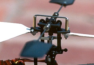
Modified antirotation link.
The complete item weighs around 5 grams. It may be an overkill, but I think I can now forget two persistent problems.
My various efforts to improve the controllability of the 'Hornet' seemed for a while to be going around in circles. Reducing the amount of free teeter improved things but led to a reduction in control power if carried too far. With barely any teeter the model flew beautifully, but there was very limited control.
I assumed that too great a reduction was interfering with flybar operation due to introducing friction in the flybar teeter. This was improved slightly by using piano wire instead of the my original PCB packers. The wire was inserted inside the hole in the rotor head and meant that there was only a very small point of contact between the wire and the boss on the head pivot (E044). Again, slightly better, but not the improvement I hoped for.
At this point I realised that the actual movement of the swashplate was severely limited by the way it fitted on the shaft and I was overdriving both cyclic servos. Careful adjustment of the ATV sorted that one out but I now had even less control power. Small wonder that many people are using reverse exponential (that's positive expo to Futaba users). Unfortunately, my brain is linear and I could see no advantage in going down that route.
At this point I ordered one of Chris Rigoleth's swashplate ball modifications, which meant that I should be able to get more swash movement.
With 3/8" of free teeter and 30% more travel than the swashplate could accept, I had a set-up that I was comfortable with, but I still hadn't flown it outdoors.
My feeling at this point was that the whole rotor head was just too stable. With the amount of flexibility in the head and all that teeter, it took a lot of effort to make it change direction and there was a big time delay before any change communicated itself to the rest of the heli.
I had been flying with the flybar weights located as far in as possible after the first few flights. The reasoning here was that the flybar needed to respond as quickly as possible in order to reduce the response time. It also reduced the head stability.
One short flight with the weights in the outermost position was all it took to convince me that my reasoning was spot on! The response was far slower.
At this point the fifty third flight produced the crash detailed above and I changed to my brass shaft with double antirotation link.
As an experiment, I removed the blades and ran the model up to hovering speed (by ear). I then tried adding cyclic inputs to see just how quickly the flybar responded. It was very slow, but the surprise was that the joint between the mast stopper and the main shaft failed, allowing the shaft to move down and disengage the tail drive. The reason for this was obviously that the blades were no longer pulling the shaft upwards and the force that the flybar was able to exert was quite considerable. Far more than I would have expected!
Another thing which became very clear was that the servos were moving. I had plates that were the same size as the servo securely glued in place with the servos attached over the full area with a single layer of thin servo tape (Futaba). Pretty secure I would have thought, but they were moving. Simple solution - one mini cable tie around each servo.
The next flight was much better. I now felt like I really had control over it the whole time. At this point, the steady gale that had been blowing for the last 6 weeks dropped to a mere stiff breeze so I just had to try the model out of doors.
What had seemed like a fairly calm day actually turned out to be a 10 - 15mph breeze with frequent gusts. Surprisingly, the model coped very well. The only real problem was that it would kite up to 10 - 15 feet every time there was a strong gust. I had to shut the motor right down to kill the climb and then add a blast of full power to kill the following descent. Control was good and I was able to do figure eights and circuits. It was surprising that the tail had enough power to turn the model downwind.
The next day was much calmer and I rushed out for another flight. Something was clearly not quite right and I got into a repetitive cycle where the model would pitch up and reverse downwind. On two occasions I turned the model away into a downwind dive, recovered and brought it back. On the third time I didn't make it and the model hit the ground - with no damage!
The reason for this behaviour was immediately obvious. One blade was very loose and would not stay in the correct position. I found that the nylock nuts used to secure the blades would actually come loose if the blades were moved in the direction of the thread - forwards on the head. A touch of threadlock sorted that one and another lesson learned.
At this point, Chris Rigoleth's swashplate ball conversions arrived (I ordered two) and this allowed me to add the icing on the cake with proper location of the swashplate. The difference was very obvious on the next flight. An additional bonus was that I was able to get more swash movement than with the standard system.
Things never seem to stay right for long with the 'Hornet' and a degree of vagueness crept into the control response once more. This turned out to be due to the flybar teeter (E045) becoming loose. The problem was that the bearings were badly worn, because they are very porely located by the two grub screws. This also places a load on the plastic Pivot Support (E044). Aluminium pivot supports are available from John Kallas which help here, but the real problem is that the grubscrews are too short (3mm). 4 or 5mm long screws are much better. In my case, a pair of new bearings were also needed.
A significant reduction in flight times heralded the departure of my second motor pinion. I ordered 4 this time! Once again, there was wear on 3 teeth which were adjacent to each other. I had become aware of an increase in gear noise and had adjusted the mesh to give some small play. The gear failed in two flights. It would appear that too tight is better than too loose. A tight mesh will wear to fit and should then last for some while.
The method of supporting the battery is very fiddly. I originally discarded the small plastic hooks which hang from the longitudinal struts between the U/C legs and simply hooked small rubber bands around those struts and around the battery. This was better but still fiddly.
I now loop the bands around the struts and through themselves so that they are permanently attached to the struts alongside the motor. A piece of 1.5mm carbon rod is mounted above the struts using miniature bands cut from silicon fuel tubing. This can be pulled back to make it easier to attach the rubber bands to the ends after passing over the battery. Finally, this rod can then be pushed forwards to snug the battery up against the motor.
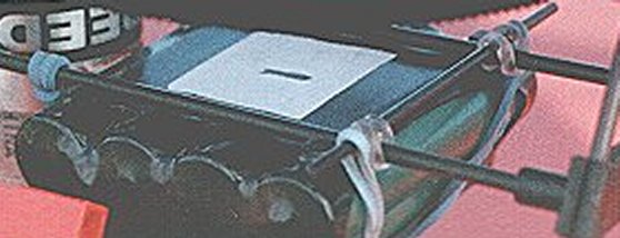
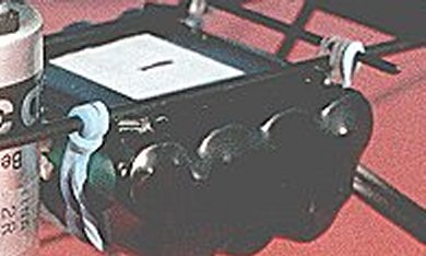
I attached pads of plastic card above the battery to locate against those longitudinal struts, so that the battery cannot move sideways and escape in a hard landing. By suitably locating four small squares at the corners of the battery it is possible to mount it with the cells lengthwise or crosswise. A piece of foam rubber can be mounted on the rear of the motor to adjust the battery position if needed.The bands should be crossed over below the battery to further discourage it from escaping.
My original Speed 300 motor showed a dramatic drop in performance at 114 flights. This coincided with my trying an 8 cell pack of 720 mAh Sanwa NiMH batteries, though I'm sure that is coincidence.
The flight times had always showed some variation, usually accompanied by an increase in noise. This sometimes indicated a worn motor pinion. At other times I would get a drop for a few flights, which would cure itself. Flight 105 was a particularly good one at 9:40. This declined over the next few flights to below 8 minutes, all on the original MS 7 cell 700 mAh batteries. Flight 113 was the first on the 8 cell pack and was 8:13. Number 114 on a 7 cell pack was just 3:03 and something was clearly wrong because it would barely climb out of ground effect after the first minute.
I removed the end plate from the motor and found that the commutator and brushes were very dirty. The brushes were well worn. I cleaned everything with cellulose thinners, which left the commutator very dark in colour. I polished this with very fine wet and dry paper and reassembled the motor. Another flight on the 8 cell pack gave 7:50. Better but not good.
Fortunately, my local shop had a Graupner Speed 300 in stock. I looked at the brushes through the holes in the motor can (being very short-sighted has some advantages) and found that the brushes have the middle relieved with a small piece at each end in contact with the commutator. This motor came with an instruction sheet in 4 languages. The relevant bit looks like this:
'Short-time' could mean a lot of things!. I think must people who use small electric motors would say that running-in is essential. Maybe the brush shape would speed things up but it would not be tolerant of abuse during the first run.
I ran the motor in for 2 hours at 3 volts (from a model railway controller) and the brushes lost their raised part and the commutator became polished over the full width of the brushes. The first flight, on the 8 cell pack, gave 8:59. The next flight on a 7 cell pack gave 9:10, followed by one on the 8 cell pack at 9:28. This was only the fourth flight of the 8 cell pack.
I do have my doubts about that 8 cell pack. Many others report better power and longer flights from the additional cell. The claim for longer flights really mystifies me. More volts equals more current. More current equals shorter flights. Maybe you are running at a lower setting on the speed controller, but you should be taking the same current. If you are lifting that extra cell, it still equates to more current.
The sixth flight on the 8 cell pack heralded more problems. The motor sounded very hesitant and shut off after only a few seconds flight. A closer look showed that the servos weren't responding and the light on the gyro was out. After a short wait, the light came on very hesitantly and the servos started to respond jerkily. A look at the speed controller nearly gave me a burnt finger - it was very hot.
A process of elimination showed that the problem stemmed from the tail servo. Unplug it and everything worked fine. Plug it back in and the ESC started to get hot. Move the tail servo and the ESC got hotter and shut down. I had always wondered about the advisability of running 3 servos and gyro from a speed controller that was probably designed for two servos. The heatshrink covering on the ESC had split and I could see that the voltage regulator chip was a very small one and that the heatsink had been cut off so that it could be soldered onto the circuit board.
Although it appeared to be working again, I removed it and fitted an external voltage regulator, complete with heatsink. The servo was replaced with a Hitec HS-50. This improved the tail response and stabilty dramatically. I am now considering replacing the two cyclic servos, for obvious reasons.
On the face of it, it would seem that the 8 cell battery pack has cost me a motor, a servo and a voltage regulator. All this for no improvement in performance. The flight times are about the same as they were on my 7 cell packs when they were new. Right now, I'm seriously considering removing one cell. It would certainly make it easier to charge. At the moment I charge the 8 cell pack from a 13.8 volt regulated supply as per the MS charger instructions.
I'm charging via a Kastner milliamphour meter and my two 7 cell MS packs show around 720 mAh (after 60 cycles) each, while the 8 cell pack shows 810. The 7 cell packs are both now down to around 8 minutes flight time. This compares with the longest ever flight at 9:44. The last minute of each flight is now in low ground effect, so the effective useful flight time is little more than 7 minutes.
The 8 cell pack currently gives just over 9 minutes with a very short 'dump', so the useful flight time is over 8:30. I always fly until the model is solidly grounded and then run the model at full throttle in my hand until the speed controller cuts out. All three packs still run for about 9:20 overall. That's my real yardstick. Anything less than that and I start looking for problems with the heli. Note, however that the 7 cell packs used to run for considerably longer than this, while the 8 cell pack has lost only a little.
I tried slow charging the 7 cell packs, followed by a discharge at 700 mA and then another slow charge. This lost me about 30 seconds flying time on each!
Further experience shows that anything other than a normal fast charge (760 mA) produces a drop in performance and flight time. This drop is never recovered! After two or three normal cycles, some of the flight time will return, but not all.
At 175 flights, my second motor showed a marked drop in performance. This motor had never been as good as the first and I am sure that the difference lies in the running-in procedure. Somewhere on the Hornet forum I saw a suggestion to use a model train controller for running in. This seemed like a good idea as I had several. During the process I noted that there was quite a lot of sparking at the motors brushes - which is not good.
Following the drop in performance the brushes and commutator were very worn and dirty as with the first motor. What was also clear was that the magnet strength was lower. Turning the head of the heli against the motor gave very little feel of 'cogging' by the motor. I now remembered the correspondence in various magazines some years ago about the fact that low frequency speed controllers could have a bad effect on ferrite motor magnets. Model train controllers are low frequency.
Meanwhile, my local shop didn't have any Speed 300 motors in stock, so I reinstalled motor number one with a cleaned commutator and brushes (and pinion number three). It was immediately better than number two had ever been with flights back to around eight minutes.
Motor number three will be run in by my usual method of running for several hours on a low voltage - and pure DC.

![]() Back to Hornet index.
Back to Hornet index.
Still more on motors - More FP head mods - The tail
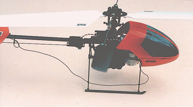
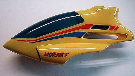
I acquired a 'GPH' style canopy from JMD Models (shown above). This is nicely moulded in two halves which are joined with tape. I masked off the edge of the windscreen area on the inside with narrow lining tape and brush painted the inside with Humbrol enamel. After this had fully cured I sprayed the inside very lightly with car cellulose to tint the screen. Trim lines and lettering were applied on the outside with more enamel and a bow pen.
The finished weight is a little heavy at 17 grams and it is a very tight fit on the FP 'Hornet'. It would require very careful positioning of the servos to get it to fit a CP machine.
In fact, motor number three was run-in underwater. I had read about this and wanted to give it a try. I immersed the motor in a glass of water and ran it for 15 minutes in each direction on two large nicad cells (2.4 volt). The water assumes a curious silvery appearance, which I think is caused by air bubbles.
After drying out and oiling, the motor felt very smooth and has always run well.
At this point the plot thickens considerably because I sold two IC helis and used some of the proceeds to buy a second 'Hornet' This was built as a collective pitch model and will be dealt with on a separate page. For the record, the motor (motor 4) was run-in for several hours on 2.4 volts as with my original motor.
Thanks to my friend Joe Hussey, I have been able to examine an example of the Ikarus 'G-310' motor which is sold as a more powerful motor for the 'Piccolo'. There have been comments on the 'Hornet' forum that this motor is unsuitable for the 'Hornet', without any real explanation. I can now reveal that the motor has been 'timed' by advancing the brush timing. This is done by rotating the end of the motor which carries the brushes against the direction of rotation.
Why won't it work on the 'Hornet'? Because the motor rotates in the opposite direction in the 'Piccolo', so if you fit it to a 'Hornet', the timing is retarded, rather than advanced. I intend to try this on a standard 'Speed 300' and see how it goes in the 'Hornet'.
My early modifications to the FP rotor head consisted of removing most of the free teeter by packing. I became convinced that the real answer was to eliminate the teeter completely but couldn't figure out how to do it without seriously interfering with the flybar action. I tried putting a pin through the head from the side, but it became clear that I would have to modify the head pivot (EO44) to allow clearance for the pin when the flybar tilted. I left things alone until the purchase of a second kit gave me a complete head to play with.
The vertical positioning of the pin is quite critical. It needs to be as far as possible away from the flybar to reduce the effects of leverage but close enough to still allow the flybar to tilt normally.
This produced a very stable model in the hover, but with very restricted control response. The obvious way to get the response back is via the time honoured method of lightening the flybar paddles. The standard plastic paddles weigh around 5 - 6 grams for the pair. I made up a set of balsa paddles from 3/16" sheet and of roughly the same area. They weigh less than 1 gram and gave exactly the response that I wanted in the hover. I now felt completely comfortable hovering in a confined space.
The downside became apparent when I was able to fly in a large hall and indulge in some forward flight. It was clear from this that forward flight stability was more akin to a flybarless model and needed some care. Nonetheless, this does allow you to tailor the response by adjusting the paddle weight. I intend to refit the flybar weights to make this easier.
There has been so much posted about the tail on the various forums that most people contemplating buying a 'Hornet' must think that there are serious problems. They have certainly been given the impression that several modifications are required to make it work at all. The real problem is that so many expect the tail to be something that takes care of itself, aided by the gyro. This simply isn't true of any model helicopter and certainly not of a miniature plastic machine intended mainly to be flown indoors. On any machine you have to fly the tail all the time and it will not take care of itself, especially if it is a fixed pitch model.
The tail on the standard 'Hornet' is fine if you are used to flying model helis. Most problems can be fixed by learning to fly it. However, there are three problem areas:
1 The geometry of the tail pitch bellcrank, the pin-in-a-hole linkage to the slider and the slider itself. This actually requires some slop in the slider to work at all and fitting a better slider can make things worse.
2 The fact that the slider is moving along a carbon fibre shaft, which is not the most slippery material around.
3 Compared with the rest of the tail system, the tail blades are relatively massive. The centrifugal force which they generate can only make all the other factors worse.
For the time being, my FP model is remaining completely standard because it works well enough. However, I am trying various 'cures' for the above on my CP machine. One thing that I have established so far is that a dual bearing pitch slider is not the answer.
![]()
![]()
![]()
![]()
![]()
![]()

![]()
![]()
![]()
![]()