The kit - Mechanical assembly - Fuselage assembly - Flying - Future developments - Conclusions - Helimax 80 - Specification
To be more accurate the kit should be called the 'Helimax 60/80' but the '80' applies to the 4-stroke version of which more later.
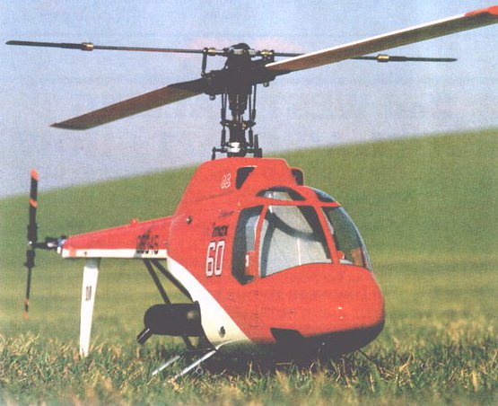
The 'Helimax' has been around for some time in both '40' and '60' versions. but does not seem to have attracted a lot of interest. This is rather strange since the 60 version gives a model which uses the well-proven Ewald Heim design rotor head and blades with 60 power in a helicopter weighing only 9.75 lb. This must have enormous competition potential when you consider that most of its competitors would be hard pressed to meet the old FAI limit of 5kg (11.05lb)
Differences between the 40 and 60 versions lie in the length of the tail boom (the 60 is 90mm longer), larger rotor diameter (100mm larger) with symmetrical blades, 2mm wire tail drive (instead of 1.5mm) and stronger side frames. The tail fairing is an optional extra for either version.
Packaging follows the now almost universal practice of using numbered polythene bags for sub-assemblies together with a tray for maior mechanical items The quite complex forward fuselage is moulded in just two parts with a clear canopy attached to it by screws. The optional tail fairing is moulded in top and bottom halves Blades are supplied fully finished with self-adhesive covering material. Tail blades are glass impregnated plastic mouldings. Tail gearbox is supplied ready assembled as is the rotor head and blade holders.
Radio box parts are of die-cut ply. while the vertical and horizontal tail surfaces and the two part cooling duct are plastic mouldings. The duct is transparent which allows you to observe carburettor operation - a nice touch. All linkages are supplied.including a mechanical mixer to be mounted on the aileron servo
Instructions can only be described as copious - quite normal on Graupner kits. An exploded diagram of the complete machine is accompanied by a step-by-step photo sequence and an instruction book in several languages, all written for the '40' version. An additional photo-sequence and multi language instruction sheet details the modifications for the 60 and 4-stroke versions. Confusing at first, but straightforward once you get the hang of it.
Motor mounting hardware and cooling fan are not supplied in the kit. These must be selected from a range of accessory packs to suit the engine used. Apart from the tailboom fairing, other options available include a ball-bearing set for head seesaw, paddle bar and tail rotor pitch bridge bearings, ball-bearing aileron/collective bellcranks and a pilot figure.
This was very straightforward following the instruction sequence. It is necessary to pack the ball-bearings with grease, these are then sealed by cover plates. A nice feature is the provision of shims above and below the mainshaft bearings which allows the tail drive to be adjusted by raising or lowering the main gear slightly. Other manufacturers please copy. This is useful if, as the instructions say: 'faulty backlash of teeth should manifest itself'
Starting is effected by means of a conestart driving an idler shaft down through the clutch and engaging a slot in the fan securing bolt. This complete assembly can be moved fore and aft to adjust the mesh between the drive pinion and the main gear. This should be done before fitting the engine.
A ply radio box accommodates the radio equipment and tank with the servos being mounted in its top surface. By disconnecting the linkages and removing six bolts, the complete radio package can he removed for servicing without being encumbered by the rest of the model. This is also useful if you wish to change the make or type of equipment - simply make another box. Two different top panels are supplied to cater for different types of servo. An additional wooden platform fits into slots at the front of the radio box. This is eventually attached to the fuselage moulding and supports the front section.
Tail drive wire runs in a plastic lined aluminium tube which is supported inside the aluminium tail boom by three plastic mouldings. The whole lot is held together by the helicopter flyers friend - Stabilit Express (supplied in the kit). At the rear end, the shaft is bent through 90 degrees to give a positive drive, but power is transmitted at the front end by clamping the wire in a split collet. Care should be taken to ensure a sound joint at this point.
Glass filled nylon mouldings make up most of the head assembly including the Bell/Hiller mixers, while the swashplate is all metal. There are lots of places here where careful assembly and use of the thread locking compound supplied will pay dividends.
Collective pitch control is effected by moving the swashplate up and down. This does have the benefit of removing the slop which tends to creep into fixed swash plate systems, but does add complexity. Pushrods either side of the swashplate move together for collective and in opposition for lateral cyclic control. The mixing which this entails is performed by a mechanical mixer mounted on the aileron servo and also operated by the pitch servo. Fore/aft cyclic is applied by front and rear pushrods going down to a bellcrank which is mounted on an idler arm which permits it to float up and down with the swashplate.
If required, the mixer on the aileron servo could be replaced by an electronic mixer and it should also be possible to arrange for the swashplate to be operated directly by three servos if you have a radio which incorporates cyclic/collective pitch mixing (CCPM)
Tail rotor control is applied via a piano wire pushrod running in another plastic lined aluminium tube This tube runs in close contact with the side frames, numerous bolts, etc, so I took theprecaution of covering it with heatshrink tubing to prevent any possibility of metal to metal noise
Lengths are given for all the linkages involved in the rotor head which makes setting up very easy A pitch gauge is supplied which allows the pitch range to be set up from -2 degrees to +5 degrees. Slightly confusing this since some parts of the instructions refer to 6 degrees.
It is necessary to drill extra holes to position the rear undercarriage rails 6mm to the rear to clear motors fitted with a heatsink head. Likewise, holes have to be drilled to 'safety' the undercarriage clamps and the various clamps around the tail boom, so you do have some work to do.
It is difficult to find anything to criticise in this example of Teutonic engineering, but one is forced to the conclusion that cap-head bolts and 'nylock' nuts must be very cheap in Japan!
An attempt was made to join the two fuselage halves with liquid solvent (Mekpak) but this was not too successful so - back to the Stabilit! As previously mentioned, the nose is supported via the radio box, while the rear is supported by two spacers attached to the side frames. Rubber grommets are supplied for this point and these were fitted in the fuselage sides. On reflection and rereading the instructions, I believe the intention is that the fuselage should be placed on the spacers and the rubber grommets placed on top - take your pick.
Threaded rods and spacers are used to support the tail fairing from saddles around the tailboom. Care is needed to get the holes in the right place and I did find that all the spacers need to be reduced in length to get a snug fit.
It should be possible to use most types of paint on the material used for the fuselage, but I used Humbrol enamel for safety and finished off with a coat of Humbrol polyurethane sprayed over everything, including the windows and vinyl stickers. The instructions suggest that the clear moulding should be painted both sides to prevent warping, but I did not find this to be a problem.
Power is supplied by an 0S '61 FSR-H' which had not been previously run, so I took the precautions of removing the head for the first start. This removed any problems which may have arisen from my first attempts with the cone start and also made sure that I did not overheat the plastic clutch.
Having got the motor running nicely (and re-tightened the front end of the tail drive), the head was replaced sans blades and the paddles were tracked (not many people do that). Finally, the blades were replaced and run-up for tracking purposes and we were ready for the first lift-off.
Whow! very lively in the vertical plane (you soon get used to it) and very twitchy. Things were not helped by a blustery wind and a tail gyro which obviously was not doing its job properly. A check of all the local flyers using 'Helimax's,' 'Star Rangers, etc. showed that they were all using extra weights inboard of the paddles. A call to Nigel Freeman at Ripmax confirmed that, while not strictly necessary, it was a good idea, so two 8swg wheel collets were fitted each side, which just took the 'bite' out of the response.
The gyro continued to be a problem until I borrowed a Quest unit from another model. This immediately produced a model which could be easily trimmed to hover hands off. At the moment, the model is only limited by the pilot's abilities - which is as it should be.
One feature of the 'Helimax' which is against generally accepted helicopter practice is that the tail rotor has the lower blade moving to the rear. It is generally accepted that tracking is improved if the lower blade is travelling forwards. This is a simple matter to change, but it was felt that the kit should be assembled as standard for review purposes. Once having become familiar with the model in this form the tail rotor will be moved to the other side and the results reported in 'Hovering About'.
Another development will be the fitting of a Futaba PCM system and gyro. 'Feedback' readers will see the justice of this situation!
An easy to assemble machine with aerobatic potential which, in the right hands, should be very competitive! Oh yes! And the spares are cheap!
This variation for 4-stroke engines involves the use of an alternative engine fitting kit with different drive pinion to change the gear ratio. Spacers are fitted between the undercarriage and the side frames to provide clearance for the engines cambox cover, the pitch is increased to 6.5 degrees and the metal weights are removed from the plastic clutch to delay the engaging to higher revs. The rest of the model remains as the 'Helimax 60.'
| Model' | Helimax 60' |
| Manufacturer | Johannes Graupner, D-7312 Kirchheim/Teck, W. Germany. |
| Importer/Distributor | Ripmax Ltd. |
| Engine | 0.61 cu.in. 2-stroke, 0.80 cu.in. 4-stroke. |
| Main rotor dia | 53.625 in. (1362mm). |
| Weight | 9 lb. 12 oz. (4.42 Kg) with 5 servos, gyro, 1.2Ah Rx pack and 450mAh gyro battery |
| Control Requirements | 6 channel helicopter radio (5 servos) + gyro. |

![]()
![]()
![]()
![]()
![]()
![]()
![]()