The concept - The kit - The motor and silencer - Assembly - Everything else went exactly as planned! - Installation - The canopy - Setting up - Flying - Conclusion - Specification
Anyone who has been playing with R/C helicopters for any length of time should gain a certain degree of amusement from the idea of this particular writer reviewing a 'Concept 30'!
Having been present at the original UK launch of the machine, and having finally had the opportunity to try this latest version, I can only request that you ignore anything that I may have written about them in the past.
The 'Concept 30' line has been steadily developed through several differing machines and up-grades, culminating in the '30 SR'. For obvious reasons, it then became necessary to produce two different versions of the 'SR'; the 'SR-T' for beginners and the 'SR-X' for those who wanted to attempt the impossible. Obviously, the 'T' suffix stands for 'Trainer', while the 'X' stands for 'Expert', bearing in mind the well-known definition of an expert!
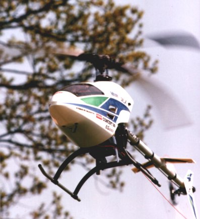
There are many differences between the two machines, but in general terms, the 'T' has a longer mainshaft, while the 'X' has many more ballraces and push-pull linkages on the cyclic controls. The main visual difference is that the 'T' has the well-known later type canopy, while the 'X' has a canopy from the Ridley Scott school of design which is likely to make Sigourney Weaver reach for her repeater rifle! If you have been wondering why it looks strangely familiar, imagine it painted a darker colour with a second set of jaws coming out of the front.
This can only be described as 'conventional' because the current state of the art in helicopter kits is such that they are all very similar. Add to that the fact that this is a Kyosho kit, and all kits from this manufacturer now have a very similar format - and a very high standard - and the poor reviewer is left with very little to say that is new. In this context, such words as 'superb' or 'excellent', no longer have any real meaning. At the risk of having Tony Wright disagree with me, there are no bad kits any more, only very good ones and excellent ones.
The format follows the well-known numbered bag system, matching numbered sections of the manual. Each section also has a full-size drawing of the relevant fasteners (bolts, screws, nuts, etc.).
Most of the major structural components are in glass reinforced nylon, while the tailboom and undercarriage skids are of aluminium tube. Main and tail shafts are steel, as is the swashplate. Parts of the mixer/washout unit are also of aluminium. All the balls in the linkages are of metal. Some are moulded-in, but many of them are held in place with very neat countersunk screws. A special tiny screwdriver is supplied for these.
The main blades are suppled finished and covered with heatshrink tube but, in common with many other kits, are not ready-to-use. It is necessary to glue on the root cuffs after removing the tubing from the areas under the cuffs. It is suggested in the manual that you mark around the cuff and cut away this portion of the tubing, but I prefer to do this in a manner which leaves some of the heatshrink material under the edge of the cuff. This is to prevent any possibility of the tubing sliding off the end of the blade! Epoxy is recommended for this in the manual, but I prefer to use slow cyano, as suggested by Miniature Aircraft.
It seemed to be a good idea to use a motor which had actually been the subject of an engine test, so that we could give a follow-up to that test, like we try to do with kit reviews. Better still, we decided to use the actual silencer used in the test too.
So, the engine is the one that was used by Mike Billinton for his test of the OS '32SX-H' in the April '95 issue of 'MHW' and the silencer is the K&S 'N-30RS' unit also used in that test. This combination gave 0.95 BHP at 20,850 RPM on 5% nitro and 0.99 BHP at 17,000 RPM on 30% nitro. I am using 'Superglo 16', simply because I am already using this with other machines.
Following recent discussions in this magazine, and elsewhere, as to whether nitro makes a motor run hotter or colder, it should be evident from the above that it produces more torque - which should also produce more heat.
The bonus of this idea was that the motor was already fully run-in. It was only necessary to run the model on the Dave Brain 'Head Loaders' to set the main needle and then get on with flying the model.
There is very little point in giving a complete blow-by-blow account of the assembly, or a description of the manual. Everything went exactly as described except for a couple of points which were probably unique to this particular kit:
One of the flybar paddles was substantially heavier than the other. Normally, this can be taken care of by a slight offset of the flybar, and you would be unaware of this if you follow the system of balancing the flybar using its own teeter bearings. However, in this case, one side of the flybar would have been something like a quarter of an inch longer than the other and something had to be done.
I am rather paranoid about the possibility of paddles moving in flight and had already attached the paddles using slow cyano, which meant that it was a little late to change them! With this in mind, I decided that there had to be an easier(?) way. Several quarter-inch holes were drilled part-way through the heavier paddle from the lower side. It eventually took no less than seven such holes to achieve an acceptable balance! A piece of black trim covered the holes, with a similar piece on the the other paddle to match.
I did this because I wanted to prove to myself that it could be done. In fairness, Ripmax had already offered to supply another set of paddles and this is obviously the right way to do things. However, the 'adjusted' set are still working fine.
Another thing that cropped up was that the ballraces which fit on either end of the flybar cradle went on slightly too far, which meant that the whole assembly could move sideways in the head mouldings. When the upper and lower halves of the head were bolted together, the position of the races was locked, but this meant that the final position of the flybar in the head was purely a matter of luck. I made a pair of thin plastic washers to space the ballraces out slightly so that they now fitted the recesses in the head, thus ensuring that the flybar was central.
The rear end of the tail drive wire has an aluminium coupling which is attached by grubscrews. This coupling has a tongue which engages a slot in the tail gearbox input gear. This is obviously meant to make a quick method of uncoupling the shaft from the gearbox. In this particular case, the tongue was a very tight fit and it was necessary to gently tap it in until it was fully engaged. I'll worry about it when I need to disassemble it!
One of the things which has received a lot of attention from the 'add-on' specialist market is that of rear-mounted rudder servos and/or tail pushrods for all models which have the fairly standard wire-in-a-tube used to change the tail rotor pitch. I have to say that I feel that the system used on the 'SR-X' really doesn't need 'improving'. The piece of wire that runs along the boom (or its plastic tube) has no less than seven support points and it is dead straight. Someone really thought about that one.
It is a well-known policy of this magazine (MHW) that kit reviews are completed exactly 'as per' and modifications, if felt necessary, are done later. I have to confess that I fitted a Midland Helicopters 'Tru-spin' fan at the construction stage because:
a) I already had one, and
b) they seem to be universally accepted as a good thing to have.
I did particularly like the endwise adjustment on the fan shroud. It is nice to have a new model where the fan doesn't scrape against the shroud.
One other departure from 'as standard' was to cover the boom with white heatshrink - purely for visibility.
The servos are all stacked neatly together at the front of the frame and the various linkages are minutely detailed with lengths given for each one. Also given are lengths/radii for the servo arms/discs. These all serve as a good starting point and only a minimum of adjustment is necessary.
Both the lateral and fore/aft cyclic controls (aileron and elevator) are of the push-pull type. This means that there are two pushrods from the servo output disc to the control point. There are many advantages to this. Not only does it even out the loads on the servo, reducing wear on the output bearings, but it allows you to 'adjust out' any play in the linkage itself. The actual connection to the output disc is via 'Z' bends in the wire pushrods. This is perfectly adequate but tends to wear rapidly. Most flyers will eventually replace these with ball-links and it seems a shame that they could not be included in the kit. I would suggest that, where 'Z' bends are used, it would be helpful if the kit included the correct size drill for these. A clear plastic gauge is included which indicates just where to drill the holes in the output discs.
I normally try to make a neat job of the wiring, but really struggled on this one. With almost every servo, the leads seemed to be just a little too short. I had a choice of using extension leads or taking short-cuts which gave untidy wiring. There are some plastic loops which snap onto the frame and which are intended to support the wiring, but these force you to take the long way around. In the end I started again, copying the layout in the manual, and found that I could get things reasonably tidy until the leads reached the receiver. This left me with some odds and ends of wiring, plus the gyro wiring, which I had to tuck under and around the receiver - far from ideal.
Things are further cluttered by the inclusion of one of Anthony Cooper's voltage monitors ('MHW' December '94) and one of Mike Stevenson's glitch counters ('MHW' February '95). More on the glitch counter in a future issue.
I am far from proud of the resulting 'buggars muddle' (perhaps someone out there could tell us the origin of that one), but most people find it acceptable.
Let's say no more about the styling - it's already beginning to grow on me (?) - but add a little about the decals. These have to fit over a degree of compound curvature and you are instructed to use soapy water to assist matters. I did this and was (and still am) far from happy with my first attempt. In full accordance with Sod's Law, I then did the second side dry and acheived much better results! A fair amount of cutting in suitable places eventually gave reasonable results, Or, so I thought until the next day! I am going to try again, but I would suggest in the meantime that you cut the side decals in two, horizontally, and apply in two sections, preferably dry.
The canopy hooks onto a tongue at the front of the frames and the 'ears' are attached by means of spring-loaded over-centre catches. The result is quite secure, but it is necessary to cut away a part of the top 'lip' to clear the elevator linkage.
A simple card pitch gauge is included which allows you to set up the basic pitch range. The manual includes a chart of suggested pitch ranges for hovering, aerobatics and autorotations, but something rather more accurate is needed for setting these. From here on the setting up procedure can be as thorough and complex as you may like to make it, but most experienced flyers will set up a basic range and then adjust things to suit by flying the model.
In this context, 'setting up' really applies only to the pitch channel. The throttle movement is simply a matter of ensuring that the throttle barrel is not driven too far and that the throttle can be fully closed. The cyclic linkages are set so that the swashplate is level and the tail rotor pitch is set to the middle of the available range. After that you have to fly the model before any more can be done.
Having no worries about running-in the motor, the first flights were something of an anticlimax. Having made sure that all the blade linkages were identical for each blade it was, nonetheless, a pleasant surprise to find that the blades were in track. A little rudder trim and the inevitable touch of right cyclic and it just sat there. This was just too good to be true!
Well, not quite! It didn't hover with the throttle stick in the middle, nor was the head speed quite right, but this was just about the best way to start that I can imagine.
Just as I was getting to grips with the machine, the weather changed for the better and I have been able to get in a lot of flying with the model. Actually, I began to like so much that I had to limit things for a while until I was sure that we had the necessary photos. (Quote from photographer, "It's so steady that I wonder whether you could hover it over me if I lie down?").
Most of the early flying was done on the kit blades which are quite satisfactory. At 90 grammes, there is just enough energy to auto the model in a flat calm, so Kyosho have got things spot on.
Having now started to push the model around it is very noticable how well the model tracks in fast forward flight - 'fast' being an understatement. It is very satisfying to do a large fast loop, even in high winds, and have the model fly dead straight and level on the exit. I had better not mention the names of some of the other models that I have been flying, but none of them do that.
There is little doubt that the canopy shape contributes to the forward flight stability. I feel that it exerts a downforce which helps to prevent ballooning.
I have flown the model on both NHP and G-Blades with totally satisfactory results, but then found to my horror that the 'normal' 53 cm blades produced by both companies overlap the standard tail blades by some 10 - 15 mm. I have since discovered that NHP produce a set of blades specifically for this machine, at 515 mm long, which just clear the kit tail blades. Alternatively, you can use 53 cm blades with the NHP '30' size tail blades which, at 72 mm, will almost, but not quite, clear each other. Another possibility is to trim the standard kit tail blades to suit as there is ample tail power. It seems a little odd that the 'SR-X' is a couple of inches shorter in the boom than the other 'long 30' size machines - perhaps the moral is to stick to the kit blades throughout.
I still haven't completely mastered rolls with the model. To date, I have always found that I get along best by setting things up so that there is no negative pitch for doing conventional rolls (in fast forward flight, that is). With the 'SR-X', this produces a loss of height and an exit in a nose-down position. I must try using some tail mix to prevent the nose kicking down when going back to positive pitch.
What I really like about the machine is being able to steam around the sky without any untoward pitching up or down.
One interesting point is the fact that, although the tail rotor slows right down on autorotations, there is still enough tail authority to turn the model. It's almost as if it has a 'slipper clutch' fitted.
The engine/silencer/fuel combination works very well and is easy to set up. The motor runs just a touch on the rich side in the hover and cleans up when going to full throttle. This ensures that there is no tendency to 'hang on' when the hold switch is operated. I did wonder for a while why there was so much blade noise from the model, but eventually realised that there wasn't. It was just that the motor was so quiet!
This being my first real experience of the 'Concept' family, I must admit to being very impressed - embarrassingly so in fact! The models capabilities certainly exceed my own by a long way - but then that applies to most models!
No doubt, the usual up-grades will appear for the model, but I really don't feel that any are necessary. Build it like it says and enjoy.
| Model | 'Concept 30SR-X' |
| Manufacturer | Kyosho, Japan |
| UK Importer | Ripmax Plc, Ripmax Corner, Green Street, Enfield, EN3 7SJ. Tel: 0181 804 8272. Fax: 0181 804 1217. |
| Main rotor diameter | 47.5 in. (1208 mm) |
| Tail rotor diameter | 9.0 in. (230 mm) |
| Length | 43 in. (1092 mm) |
| All up weight (dry) | 6 lb 4 oz. (2.84 Kg) |
| Main gear ratio | 10:1 |
| Main to tail gear ratio | 1:4.6 |
| Control requirements | 5 servos and a gyro |
| Powerplant | '28 - 36' two-stroke glow-plug engine |
