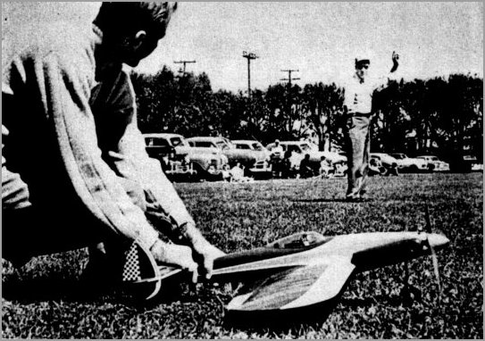
Ralph Yount holds Mars as Bob Palmer gets Set for neat take-off and another smooth hop.
Nature has created a number of problems, probably to give lots of people work, which make it impossible for an ideal machine to exist. Think of the mess if there were one ideal shape for an airplane, an automobile, a house, or anything! Therefore we must decide what we want and then slant our decisions to fulfill this end. Compromises always are necessary. Some of the data presented will be factual and proven, some will be the result of trained observation, and there will be some enlightened guesswork.
A brief word of physics seems appropriate. Airplane flight is a matter of equilibrium. Forces on a ship in level flight are balanced. Thrust equals drag and lift equals weight. When we unbalance any one of these forces an acceleration is produced in the direction of the increased force. The take-off is a good example. At the moment of release thrust exceeds drag and weight exceeds lift. The helper balances the thrust and the ground balances the weight. When released the ship moves forward and the drag builds up. When lift equals weight and drag equals thrust we have steady level flight. To climb we cause the wing to lift more so we move upwards.
The modern stunt ship did not explode upon the scene fully grown, but rather, grew up slowly. After we learned to keep a balky engine and overloaded airplane off the ground for a full tank, the logical step was aerobatics. The loop was our first milestone and it was the proud fellow who had enough power to turn a big lumbering loop. With the development of the symmetrical airfoil, we started bashing ships on inverted flight. Probably the biggest step forward was the development of the glow plug by Ray Arden, which relieved our puffing monsters of eight to ten ounces of dead weight and gradually gave us more power. Airplanes became smaller and more agile and stunt became aerobatics instead of balloon busting and wheel rolling plus 40 or 50 consecutive inside loops. Third big step was addition of flaps to the wing which gave us ships capable of the modern pattern with its square turns.
Just what makes a stunt ship a stunt ship and not a speed job? Or more simply, what characteristics do we need to stunt? The airplane must be capable of supporting at least 20 times its own weight. It must be stable for steady level flight, yet unstable enough to turn quickly without a lot of lost motion. It must be rugged due to high flight loads, yet light. Stunt ships al- most universally use a symmetrical streamline for a wing profile. This is a low lift, low drag, combination so the area of the wing compared to other types is outsized. It must also fly at a reasonable speed. The designer is allowed much latitude for artistic fulfillment but must keep proportions commensurate with full-scale airplanes. And last, but far from least, a high finish is important.
Cheer up, for you don't need a slide rule to go invertedl Hang up this handy dope sheet.
Stunt ships fall into two speed categories, fast and slow. Fast is 70 MPH and up, while slow will be below 70. The fast ship su'fers several disadvantages, such as requiring high grade rhythm and coordination an the part of the pilot. Scoring is based on smoothness and repeatability of flight paths, which require a real maestro at the controls. The slightest mistake in judgment will result in a splat! Roundness is difficult to achieve and the judges stand a good chance of snapping a neck muscle following a square turn. Fuel feed is a larger problem due to the higher forces created by high speed turns and the airplane must be lighter than if it were flown slower. However, structure must be stronger, and consequently either heavier or more cleverly designed or both. The author has seen a few people capable of this type of stunt and it's quite a show stopper, but points accumulated are usually smaller than picked up by those whose maneuvers can be seen. The author enjoys nothing better than wringing out an 85-mph Half Fast, but for money we prefer 60 MPH.
The slow airplane is not without its problems either. At lower speeds, tug must be achieved artificially. However, the maneuvers, by being slower, can be flown through, with minor corrections in attitude being made during said maneuver. For instance, the recovery from a wingover is made at 4 feet. At 85 mph this 4 feet is used up in 1/82 of a second or this is the difference between a good pullout and a basket of pieces. Most judges like to see the maneuver and will give better scores for patterns where they can see everything you do. Your fuel flow problems will be easier solved and your airplane will undoubtedly last longer. The choice is yours and we'll show how to get either type.
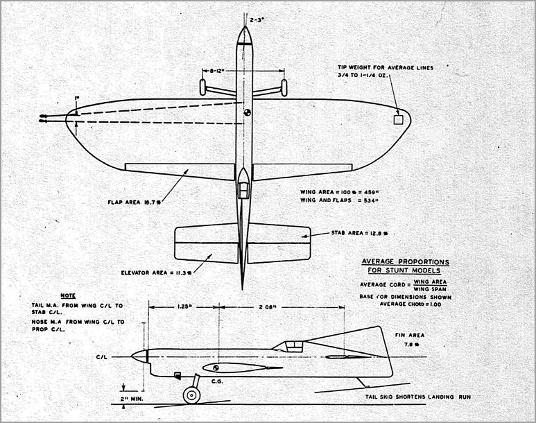
In order to determine the size of our wing we have to start somewhere making assumptions. This is where experience helps. The formulae we will present are surprisingly close to the truth, hut allow some latitude for errors which we take advantage of in our original assumptions. Much of the following information is printed in more detail, including some airfoil charts, in the 1951-52 Model Aeronautic Yearbook. Frank Zaic was kind enough to allow us to modify and present his work on Stunt Models. Let us assume an average large airplane with 432 sq. in. effective area - power from a .35 engine - giving a level flight speed of 60 MPH - wing span 50 inches and average wing chord 9 inches; built without flaps, it should weigh 2 pounds. That's enough for now.

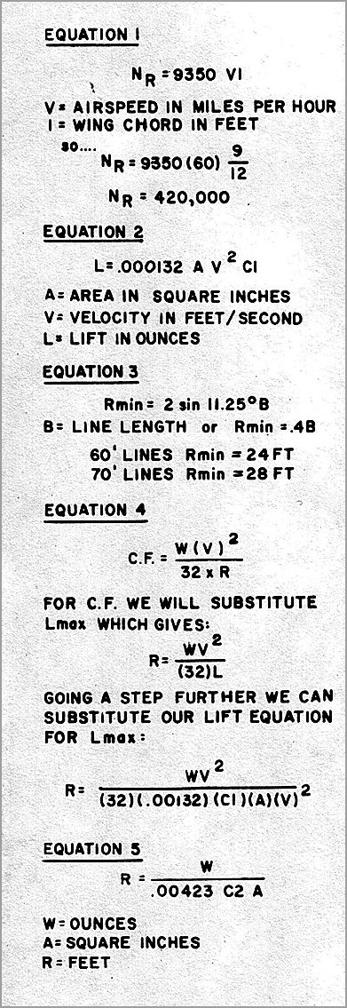
First calculation is the Reynolds number. This number is a dimensionless constant at a fixed airspeed and wing chord. The higher the number, the more closely the airfoil works as it does on full scale aircraft. Normally it is used to allow accurate data to be produced with small airfoils in wind tunnel tests and to convert this into data useful for full scale use. Full explanations of this may be found in the Model Aeronautic Encyclopedia No. 2. For our stunt model it will be as shown in Equation 1.
Sounds big until we consider full sized Reynolds numbers run around 20 million. We will use this as a tool to look up lift coefficients from graphs. However, for our comparatively narrow range of Reynolds numbers and airfoils we shall list maximum lift coefficients for the more commonly used sections. At the end of this series of articles will be a list of books from which more specific and detailed data may be derived. Our Reynolds number mainly says "An airfoil shape can be made to do more work per unit area by increasing the chord of the wing or the airspeed." But it takes large changes to produce much increase in efficiency. For general use maximum lift coefficients will be as given in the illustrations.
All symmetrical airfoils, at low angles of attack, will develop a Cl of approximately .1 for every degree angle of attack, hereafter called AOA. What's Cl? It is a number used to define the lift capabilities of a particular airfoil at a given AOA and varies with Reynolds Number. For this lift equation see Equation 2.
 |
Thus by knowing all but one of the components of this equation we can readily find the unknown.
Let's look at our model In level flight. Lift must just equal weight so let's see what AOA we need. The main calculation we are interested in is the looping radius of our ship. We are required to turn smooth loops under 45 degrees. On any length line we can calculate our required radius from Equation 3. With longer lines we have more room for turning. To calculate the minimum turn radius for our ship we will equate the maximum lift with the centrifugal force. Actually this is not exact, but for our purposes will do. (See Equation 4) Here we come across something interesting. Notice V2 in both ends of our equation. This says the loop radius does not depend on velocity. In fact, this is true for small differences in speed, but remember our speed determined our Reynolds number, which in turn deflnes our Cl max. However, it has been found that dropping V2 gives effective results so we won't bother with it. Just don't lose sight of this point. See Equation 5. To see how tight our ship will turn with a 12% airfoil, see the illustrations. This is under our miniinum for 60 ft. lines so our ship would be alright for the loops. With an 18% wing we can cut the radius to 16.2 feet and with flaps she comes down to 11 feet. All this by changing our Cl. It should be noted here that thicker airfoils are capable of flying at higher angles of attack hence developing more maxirnum lift, but that they stall more abruptly. The 18% section works like mad, but will suddenly fall out from under you. The thinner wings stall gradually and con- sequently make smoother landings. We will find that a 15% airfoil with flap is our ideal setup. Our radius with flap was 11 feet meaning a 22 ft. diameter loop. How about these 10 foot loops and smaller? We have a Pretty good good airplane for a sample. The small-diameter loop is possible and has been performed many times, by the author and others, but it is not a loop in the sense that it is at a greatly decreased airspeed. We prefer to call this maneuver a somersault since it depends on a large increase in drag and then tumbling the airplane about its wing. A loop is performed with little noticeable decrease in airspeed, although we know there must be some, since drag increases as we increase our AOA. We normally compensate for this by setting the engine rich in level flight and allowing it to peak during a maneuver. Since we are interested in the 5-foot radius let's work our equation using a 2 lb. airplane, Cl of 1.6 and determine what area we need (See illustrations). A in the formula equals 950 sq. in. which is more than twice the size of our wing. To build a ship this size to a 2 lb. weight is a real challenge. Also this size airplane would probably need a larger engine, would get heavier and larger and heavier and up we go. It might be possible with a .59 engine and a 3.5 lb. airplane. Area wouid be 1600 sq. in. Quite a beast. |
The 5-foot radius is important to us on the square turns. And strangely enough people turn them every day. How? On the slow (60 MPH) airplane our theory is this. With the sharp application of control the plane noses up sharply and slows down at least 20 MPH . The wing becoiiies stalled, but remember that it will still develop maximum lift. The wing acts as a blanket to kill horizontal motion and generate additional lift due to fiat plate area moved against the wind. The ship partly skids around the turn. The lighter they are, the better they look doing this. As control is returned to neutral, the thrust is able to take over and literally haul the ship around on its bootstraps. We will show later how to trim the ship for best square turns. With the fast airplane the small radius is largely an illusion caused by the rapid change of direction. This has been observed in careful study of the Half Fast in flight. Flaps help by Increasing lift and drag during the turn. The 5-foot radius turn, while not being a constant-speed maneuver, Is an actuality for most normal stunt ships.
It has been stated that the symmetrical airfoil develops a Cl of .1 per degree AOA. It follows that at zero degrees no lift is developed. This is quite correct and causes some headaches, mostly with airplanes flying around 85 to 100 MPH, particularly the all wing type. It shows up in a hunting action while you are forcing the ship tofly low around 4 feet. Hunting consists of the ship alternately climbing and diving, both very slightly, usually twice per lap, but sometimes faster. The condition occurs because at high speed the wing must be held at a very small AOA, say one quarter degree or less. At higher altitudes the wing must lift more, due to its tilted or banked condition and the line weight. In level flight a minimum AOA occurs since minimum lift is needed. The difference between zero and our shallow angle is quite small and at times we actually get zero lift. The model drops, but the motion of the air is then such that it develops a positive AOA and climbs slightly. There is a visible lag Involved which gives us our hunting. Actually, the wing cannot find the right AOA to support the ship. Solutions for hunting are severaL Slow down, increase the weight, sharpen the leading edge radius slightly, add roughness to the leading edge to create some turbulence (not in Combat however), or balance the ship more nose heavy. The latter two solutions aren't necessarily desirable since one is illegal (In combat) and the last will make the ship sluggish. This is an argumont for the slow stunt ship. With a hot combat wing some hunting can be tolerated in order to cram the last few ounces of lift in a turn. In stunt however, a great deal of time is spent at four feet so the problem must be considered. It should be stated here that for two airfoils of like thickness, one with a smaller leading edge radius will stall at a lower angle than one with the larger radius. Hence, more lift For looping.

Be back next month with dope on Flaps, CG, tug and other matters.

![]()
![]()
![]()
![]()