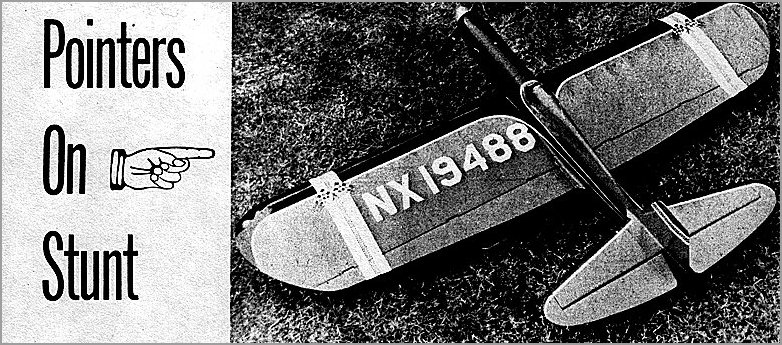
This is the fifth and last of a series of articles covering the whole field of stunt model design.
Proportions, areas, what to do, not to do, summed up in plain English.
.
Last but not least, rudder offset helps only when landing, surprisingly enough. In full flight the offset reduces drag, but does not effect tug too much. If you've ever flown after knocking off a rudder you were probably surprised to find no change in tug. The rudder does help on the upwind side, by creating a weather vane effect which helps keep the nose out.
We have found that side area should be concentrated behind the line leadouts to keep good tug in the wind. The Nobler is a good example of this.
On the subject of moment arms there is much controversy. We will evaluate their various affects and the choice is yours. Those of you who expect a cut and dried formula are out of luck 'cause it doesn't exist. Ability to snap depends on the moment of inertia about the CG. There's a formula for it in your physics books, but our system is complicated somewhat by nonuniformity of weight distribution forcing us to fall back on generalities and cut and try methods. The engine is the largest concentrated weight and it follows that the closer it is to the CG, the quicker our ship will react, all else remnining constant. Unfortunately, all else does not remain constant. A short nose and a long tail moment generally leads to a tail-heavy ship with lead in the nose. If we take two elevators of equal area and motion, one on a long moment arm and one short, the longer will generate more controlling force on the wing, as proved in our earlier discussion. In the practical sense we shorten the tail moment arm proportional to the nose moment and increase the elevator area. Examples are the instantaneous reaction of the all wing models. In stunt, however, the ability to pop around corners is overshadowed by the necessity for smoothness. So we use a long nose and fairly long tail.
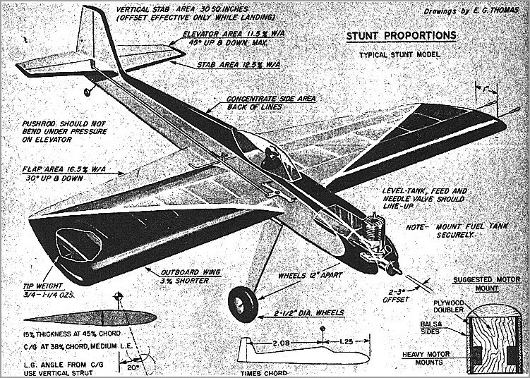
When transferring dimensions from one size ship to another it seems realistic to base dimensions on the wing chord rather than the span, for our purposes at least. Normally, the span is jockeyed to obtain the proper area, while our chord affects Reynolds Number, or efficiency, hence controlling our basic assumptions.
A few words about the fuselage are appropriate here since we must have one to hold the wing and tail as well as engine, landing gear and pilot. Area distribution is worth watching. Keep nose slim in side elevation and concentrate area aft of wing with fin area about 30 sq. in. for most large ships. Front end should be built rugged and stiff with rigid engine mounts. A light mount, as found on many profiles, vibrates badly giving poor engine run by causing inefficient engine operation and fuel foammg. Keep the rear end structure fairly light weight but don't sacrifice strength, since elevator loads get pretty high in stunt. Again rigidity is important. The slab-sided fuselage with planked or sheet-covered contours top and bottom is simplest and lightest to build and can be doodled into interesting shapes. This phase has been covered several times in the past so we'll drop it on its head.
We've touched on the vertical CG location and its affect on flight. Suppose we look at other phases of location of parts in the shear view of the plane. Drag can be considered concentrated at a point just as lift, weight and thrust. It can be estimated by considering the landing gear drag about 25% of the total, the wing about 40% and the fuse and tail as the other 35%.
The ideal condition in the vertical plane is for the thrust line tu pass through the center of drag. This eliminates the tendency to turn tighter one direction than the other. Our elevator would work best if operated out of the downwash from the wing, but this would mean placing it high on the fin which is structurally unfeasibie. We nonnally place it above or below the wing an inch or so, and let nature taka its course, Since we have proportional control over tile elevator at our finger tips, (Hah!), we can make the minor corrections necessary without much thought. We do wish to keep it from being hianketed by the wing in tight maneuvers where the trailing air is a hig mass of eddies and burbles. If you are the artistic type who tends toward weird arrangements, tread lightly, friend. Try to evaluate what your setup will do and compensate for unusual force arrangements with control movement. Get too far off base and you are in trouble.
Now about the landing gear. We have done much research in an effort to iron out landings. Ordinary steel wire gear has a nasty habit of grasshoppering a landing when you least expect it. Reason is the high spring rate of the steel itself. You have probably heard that steel is more elastic than rubber. S'true, It stores the energy from the plane touching down and gives it all back at once. Result, it throws the ship back into the air. With masterful technique and practice, good wheel landings have been made, but we wanted something to plop down from left field with no bounce.
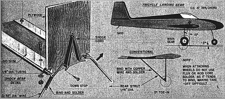
Taking a page from the light plane book, we worked on rubber-loaded gear since rubber doesn't spring back as fast as steel. Results were amazing. The gear sketched is used on the Gold Brick which tips the scale at 44 ounces. We bounced one landing out of about 40 with it. Main points to watch are: Be certain the wheels are toed in at least two degrees or more; use just enough rubber to support tile ship on a rough surface (ours collapses on linoleum) and keep the center line of the bearings parallel to the center line of the airplane In both side and top view. Be sure you install the rubber shock cords in an accessible area since they do wear out. Location of the gear fore and aft should fall on a line 20 degrees forward of a vertical line through the CG. Tricycle gear should have the main gear on a line 15 degrees from vertical through CG and aft of CG (naturally). Trike gear should track straight and the airplane should rest on the ground with the wing at about two degrees negative AOA. This enables you to hold down elevator and stick the plane on the ground. If you have a positive AOA at rest you will have no control of takeoff or landings
If the spot landing is continued a wheel brake is quite helpful. If you are not using rubber-loaded gear, use 3/32" wire on the heavier ships, two lbs. and up, and brace it at the fuselage to prevent it from flexing and bouncing you sky high. If you hit wrong you are going bounce anyhow, but flexible gear will help if your approach is good. Keep the tread wide, around a foot, use 2.5 dia. wheels or over and make sure it tracks properly.
Ted Martin has covered the engine requirements and they haven't changed at all. Keep it clean, and if possible use one engine for nothing but stunt. Get to know it like yourself. If you are in doubt about which engine to buy, we recommend a .29 or .35, and ask the man who wins consistently in stunt what he likes.
Assuming you end up with our average size airplane weighing 2 to 3 lbs., you will get the best results from a 10x5 or 10x6 prop. Most any brand with a broad blade will do. Try each and pick the one that gives the smoothest flight. The .19's run best on 9x5 to 9x6. Balance all of your props carefully to save engines, airplanes and nerves, The balanced prop is one mark of an expert. Most commercial brands are close, but the perfect balance is achieved by hand work which Is expensive.
The fuel tank has ceased to be the monster it once was. Good commercial tanks are available and plenty of information is ready for the experimenter. The October 1953 issue of MAN shows several concepts for tank layout. For most engines the three-ounce size runs about five minutes which Is about right. The author favors the rectangular tank with seven-degree slope on the rear end and a single crossover vent pipe. This was developed by Lou Andrews and is a good formula. Ask 10 guys what kind of tank they use and you will find 10 different shapes, all of which work best. Pay some attention to the tank though: Attach it securely and be sure it cannot develop leaks (at least for a while). Level it up very carefully and be certain the center line of the needle valve is on tlie center line 6f the tank, both horizontal and vertical.
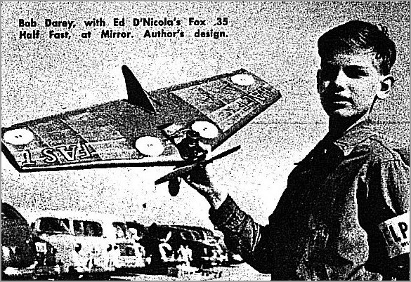
To tie the last knots in this string of information, suppose we look over one of the best stunt ships and see what does what and why. We picked Smoothie, one by the "Old Maestro" Bob Palmer, for a couple of reasons. We have built and flown it and we feel it does a fine job of slipping through the AMA pattern. Bob says he has no formula for his airplanes which means he uses a logical sequence of cut and try dimensions from one airplane to the next. The results speak for themselves. The idea was for a smooth-flying ship for use in windy weather as well as calm. Hence the area came out around 450 sq. in. with 50 sq. in. of flap, while the wing tips were made elliptical to eliminate the wobble. Afrfoil is 15% thick, at 45% of chord, which should cause the center of lift to fall at about 38%. We then have about 1.25" moment for the CG, which is a fairly nose heavy trim. To force the CG to this spot and to improve the smoothness, the nose moment arm is around 12 inches while the tail moment arm is about 16.5 inches. Stab and elevator area is about 100 sq. inches with about 45% of the area movable.
Bob moves his elevator 45 degrees max. both ways and flaps 30 degrees. The excessive elevator motion is due, in part, to the nose-heavy optimum CG location and the smaller than normal elevator area. He says the CG must be there, and my experience backs him up. The author's duplicate weighed in at 36 oz., most of them are between 30 and 38 oz. The side area is kept small and a 32 sq. inch fin is used. Landing gear Is placed well and makes for good wheel landings. Thrust line will pass through the vertical center of drag nicely. thus giving a good tug both directions. Flaps are used and follow accepted procedure on taper. I understand Bob was the first to use flaps as well as a number of other firsts in stunt design. Outboard panel is 2 inches shorter than the inboard and has .75 oz. of lead in the tip. He recommends little engine and rudder offset; depending largely on speed and CG yaw for tug wlilch is quite adequate. Recommended speed is 70 MPH and the ship goes around corners like she was on rails.
To sum all this up we would like to emphasize practice and consistency while flying. Learn what your ship will do and what it won't do. Build carefully and take your time with construction and finish. When you go to a contest be prepared to win. Be ready ahead of time. The standing joke Is a flier finishing his model on the field, but these guys are rarely in the winners circle. Learn how to relax while flying - wish I could. We go to contests to see how well our ships compare to everyone else's. if you are beaten, find out why and do better next time. We all have lots to learn and contests are the place to do it. Above all, have fun. Hope you have learned as much reading this as the author did writing it.
Model Aeronautic Encyclopedia - Vol 2, 1951-52 Model Aeronautics Yearbook; Model Aeronautic Made Painless, 1953 Model Aeronautic Yearbook.
Above available from: Model Aeronautic Publications, Box 333, Sta. D, New York 3, N.Y.
NACA Report #824 at $1.50; NACA Report #586 at $1.50. From Superintendent of Documents, U.S. Government Printing Office, Washington 25, D.C.
Model Airplane Design and Theory of Flight - Charles Hampson Grant.

![]()
![]()
![]()
![]()