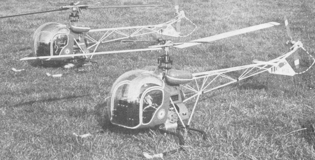
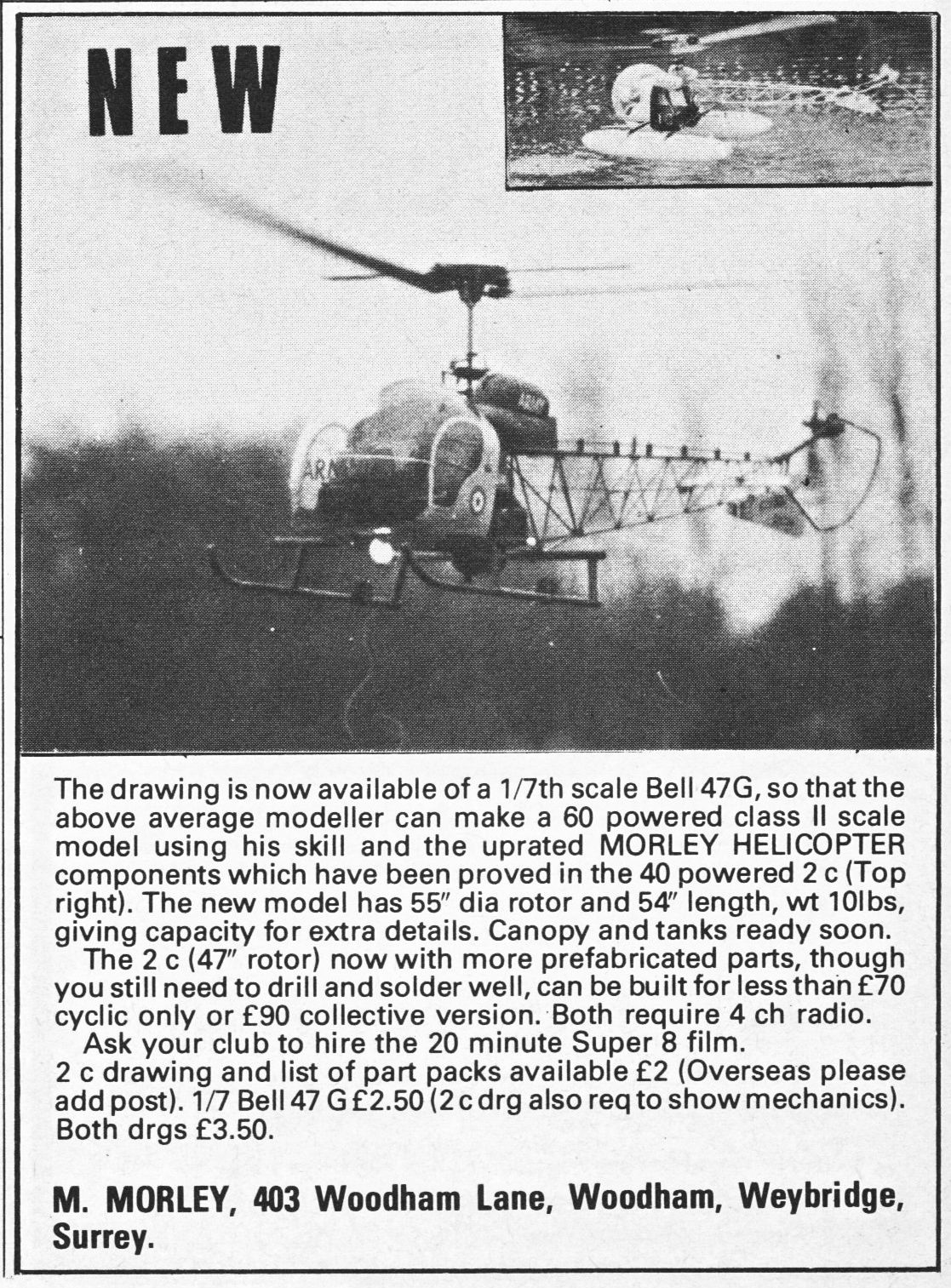
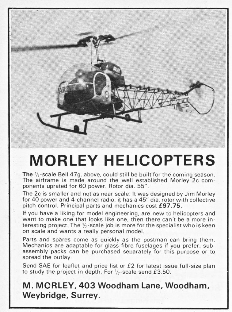
Morley Bell 47G
Morley 2B (1973)

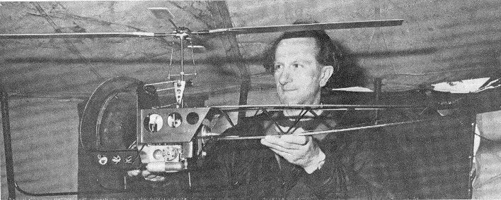
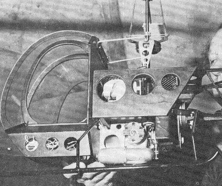
 Winning model 2B
Jim Morley had experimented for a number of years with Torque reaction type helicopters but without any real success though as he notes in the Mk2B review that was probably more due to pilot inability that perhaps model deficiency. His first Mk2 was not much of a success but this prompted him to totally redesign and build in rigidity and simplify the layout. It was with the Mk2B that in 1973 he won the first UK helicopter competition sponsored by RCM&E held at Sywell.
Morley Bell 47G Mk2B - General description from RCM&E Dec 73
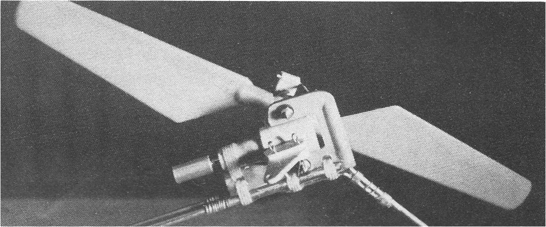
AS you can see from the above article, his first version had full collective pitch control and you can see that a number of his assumptions about control were well well in advance of the design which was different in the he used round wire to proved flap and lead lag 'hinging'. This head design though proved to be very sensitive and so he had to redesign the head in a similar manner to other he had seen that day in order to 'tame' it down.
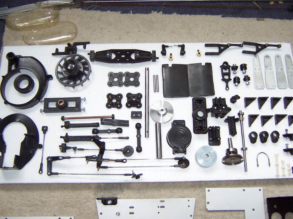
Originally brought out as a set of plans in RCM&E then following on from this with a 'semi' kit for builders being known in the 'plank' world as a "plan pack". From this you received the plans and a set of mechanical blanks from which to build the mechanics. Basically all the aluminium was cut to shape but not drilled or tapped, the clutch shoes had to be created by sawing an iron ring in half then drilling it followed by making piano wire springs. The 2B also had a wooden Bell 47 style fuselage and in many respects they were very crude with the original models not having a single single ball joint as they were not readily available back then.
Report from UK vintage heli-flyer of his experiences building an original version 2B;
My first heli, back in 1974 (!) was a Morley 2B. This was in the days before Jim Morley started manufacturing kits. Instead he produced "Plan Packs". This consisted of a plan (naturally!) and some blank bits from which it was possible to make the mechanics! There were a number of chunks of aluminium to make up the chassis. Although these were cut to shape, they weren't drilled or tapped. They had punch marks showing where they needed "to be drilled to a depth of 1", and tapped to 4BA" or such like! The clutch consisted of a ring of iron, which had to be hacksawed in half to make two shoes, drilled for the pivot points, and then piano wire springs fashioned! Ah, happy days!
Then there were the rotor blades! This was a .40 size machine, and at that time, there were no .40 size kitted helis! The only things on the market were for Schluter Cobras and the like! This machine was half that size. So I carved my own! Not being a particularly brilliant woodworker, it came as no surprise to me that the thing could barely stagger off the ground! At full throttle, it would skitter across the patch, only becoming airborne if a gust caught it and translational lift took effect! With the benefit of 20-20 hindsight, all I needed to have done was put a bit more pitch on the blades! The flapping hinges were almost certainly allowing the blades to feather, reducing my set 4 degrees fixed pitch to something more like 2! However, ignorance is bliss, and I spent many happy hours taxying the thing over the patch! One of the beneficial side effects of this was that by the time I finally *did* get it to fly, I had pretty much mastered the (gyro-less) tail-rotor!
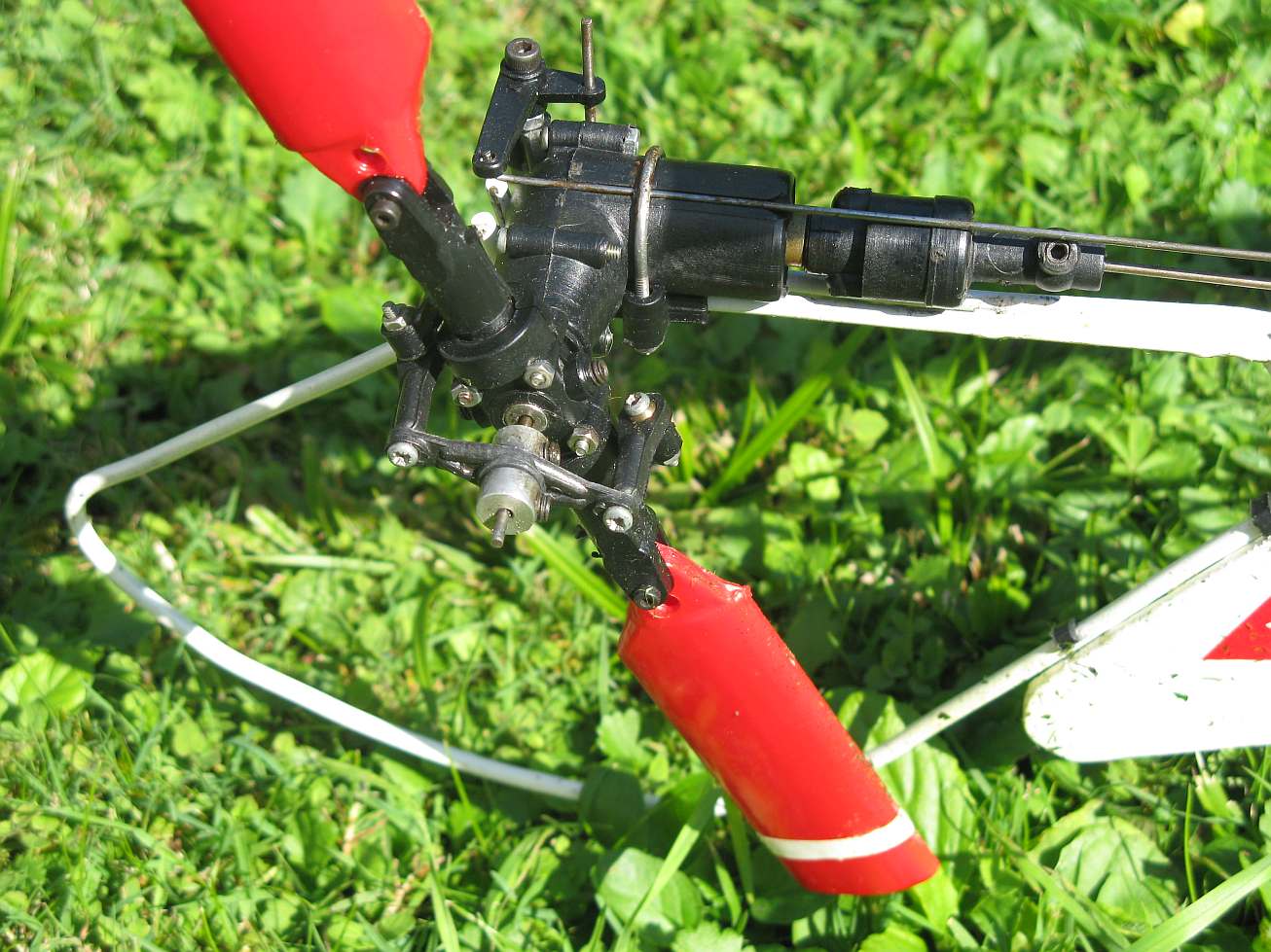
Eventually I saved up my pennies and bought a hideously expensive set of Schluter blades - and promptly sawed 6" off each to get the diameter down to where I wanted it! The machine was now airborne at half throttle! This was more like it! It was then I discovered another interesting characteristic of this early machine! The tail rotor blades were completely flat - no aerodynamic shaping at all! Those heavy Schluter blades required a fair bit of pitch, just to keep the nose straight! If you applied too much left tail-rotor (this was an anti-clockwise machine) the tail rotor blades would stall, leaving the heli gently pirouetting to the right with full left tail-rotor applied! Needless to say, for a beginner, this was an untenable position!
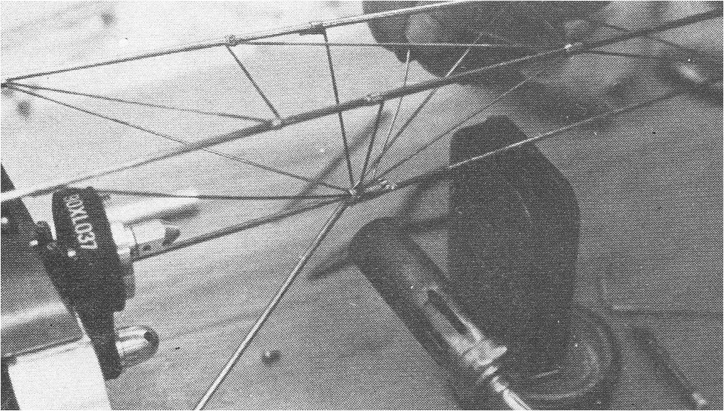
Which brings me to that tail boom! All built out of spruce and balsa strip! It took weeks to put one together, and if I was lucky, I might get half an hour's flying before I destroyed it and had to build another! Then one night, my neighbour's TV aerial blew down in a storm. Suddenly I had all this aluminium tubing in the back garden! I quickly fashioned a replacement tail-boom, and finally started to get some reliable flying!
Whilst the 2B could obviously work it was really a development prototype and was quite frail in a number of areas so Jim set about honing the design in order to make it more viable for commercial production and also to make it more 'flyable'; for this latter he had accepted that the simplicity of a fixed pitch head was the way to go.
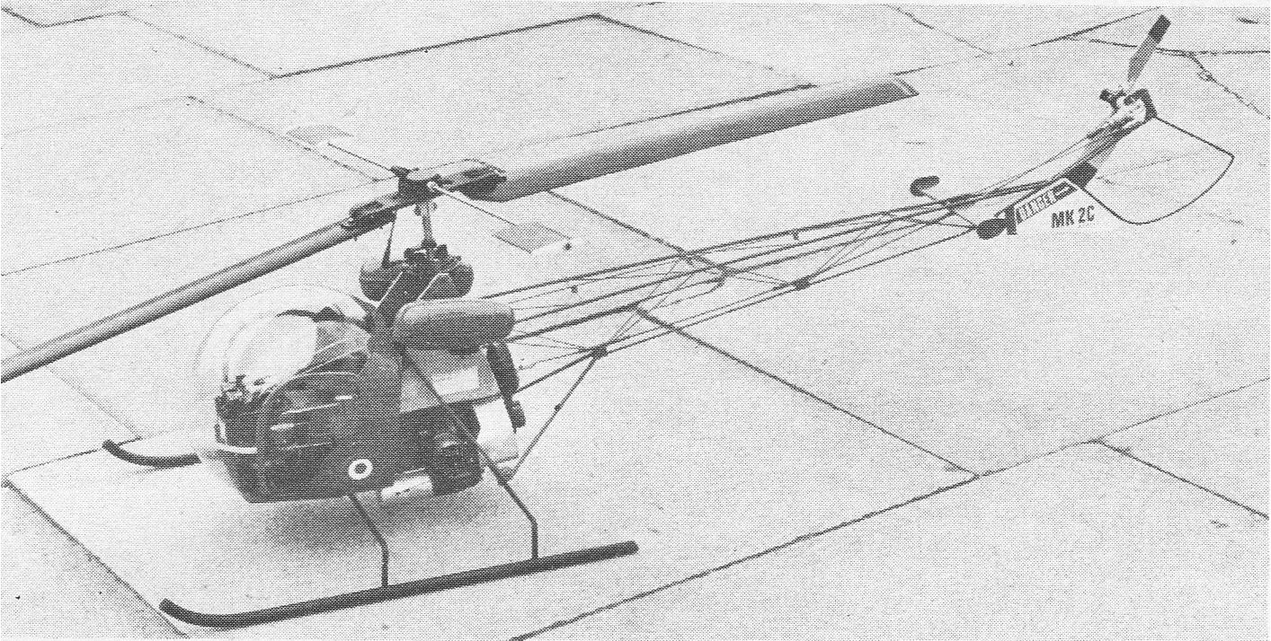
Morley 2C (1974)
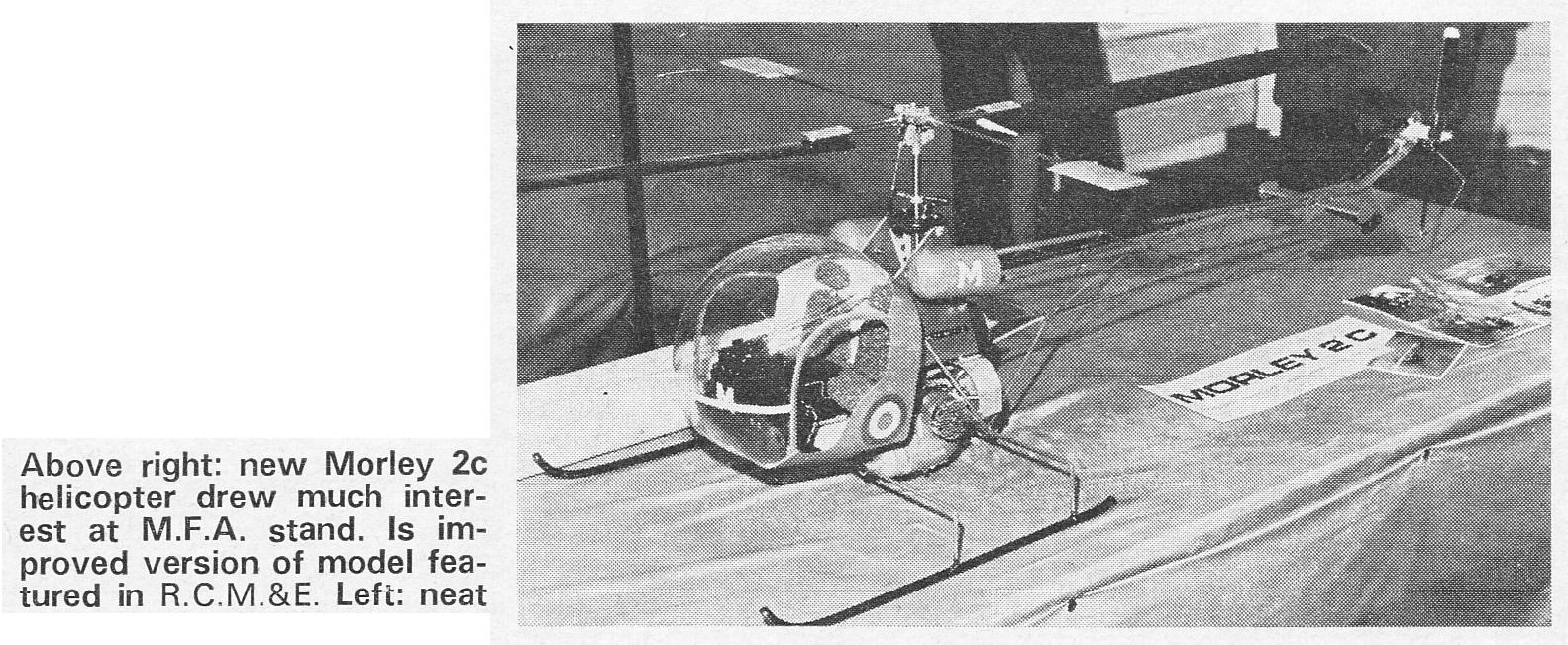 2C at Sywell on the MFA stand 1974 |
Specification:
|
||||||||||||||||||||||||
| Documents: | |||||||||||||||||||||||||
 |
 |
 |
 |
||||||||||||||||||||||
 |
 |
||||||||||||||||||||||||
 |
 |
 Parts list 1981 |
|||||||||||||||||||||||
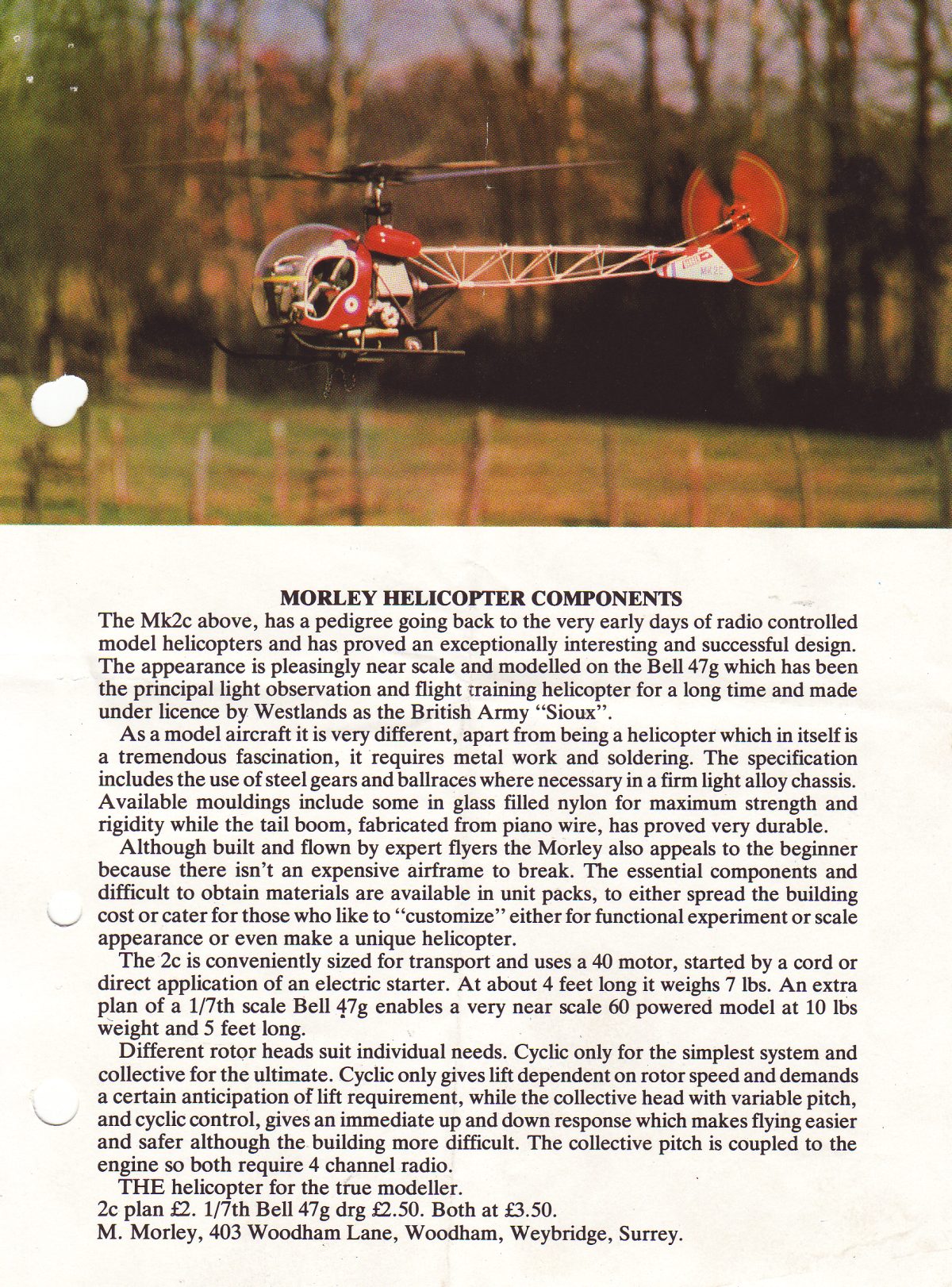
| Morley Bell47 2c, 60-size, scale 1/7 |
|||||||||||||||||||||||||
| Reports: | |||||||||||||||||||||||||
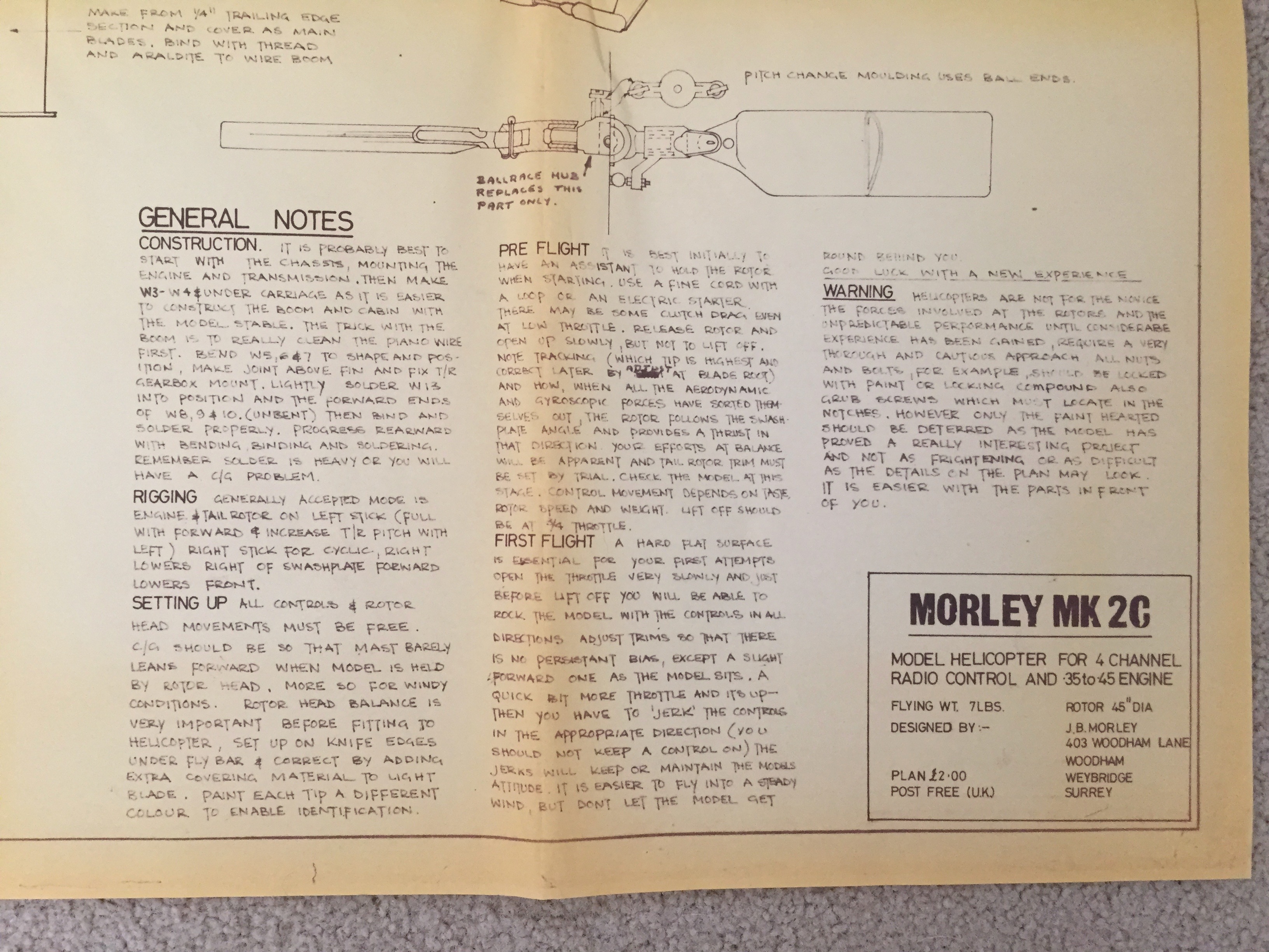
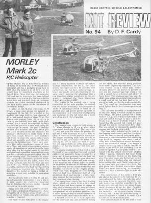 Morley 2c Magazine review - Build and flying review from Nov 76 Radio Modeller. |
|
||||||||||||||||||||||||


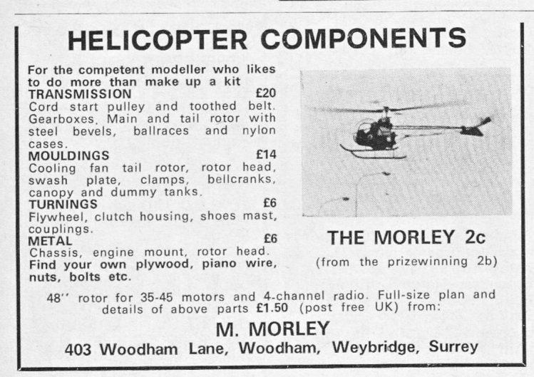 Parts advert Nov 1974
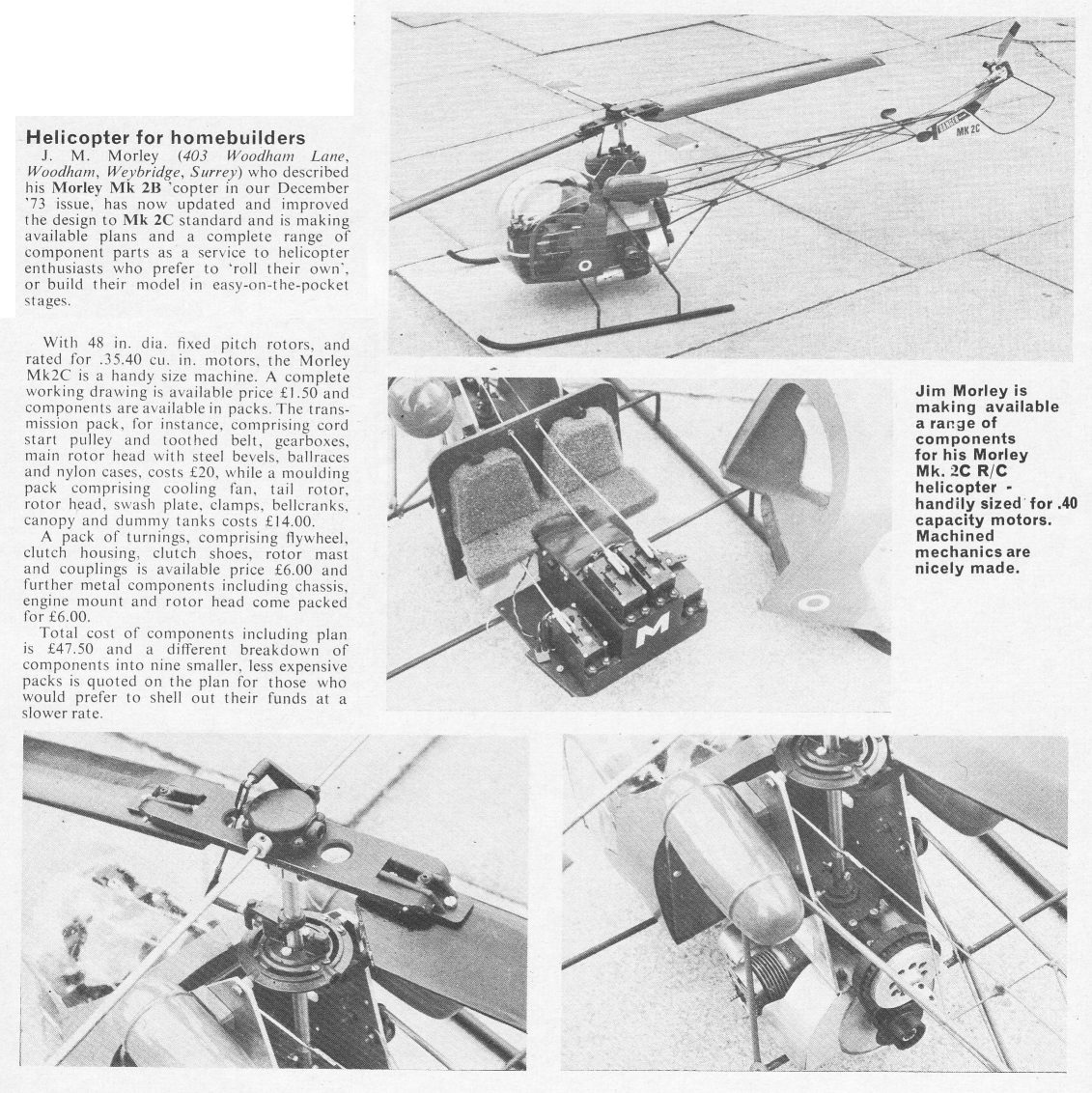
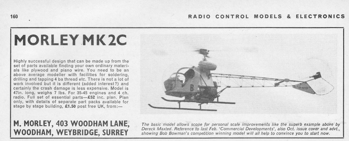
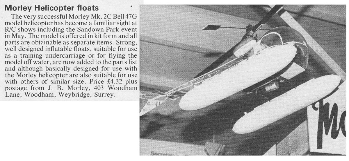
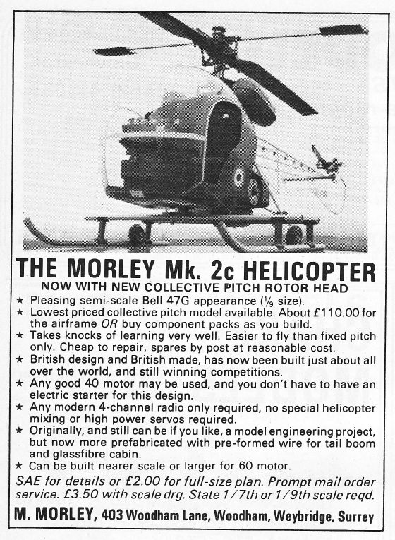
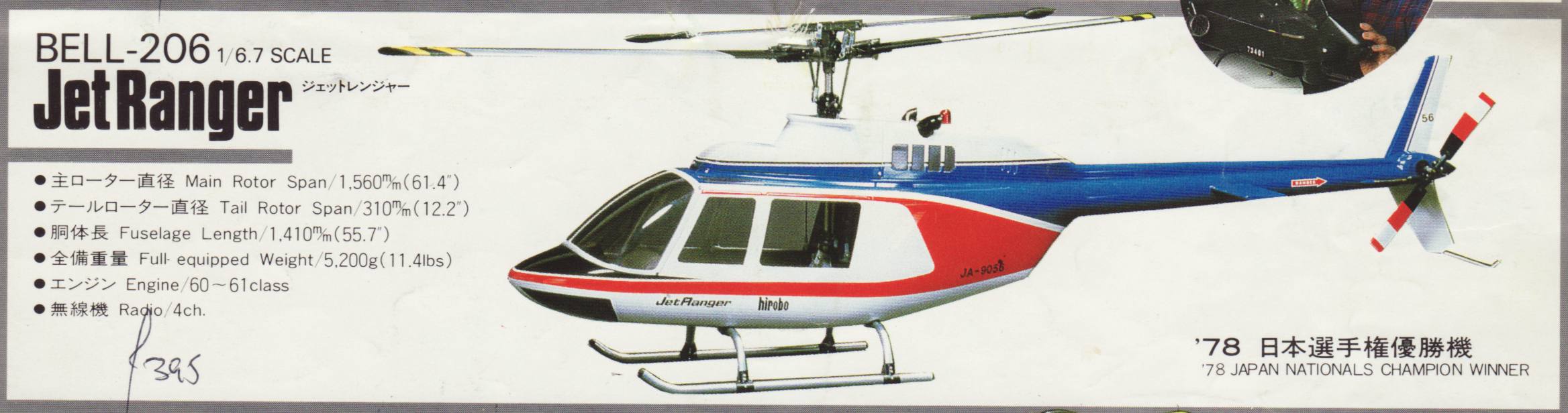
After full revision of the design and renamed 2C, in order to increase the scale fidelity he also supplied plastic scale mouldings for the bubble and fuel tanks; note early connection with MFA (who made the plastic parts???) which was to result many years later in collaboration of developing a kit for MFA to market.

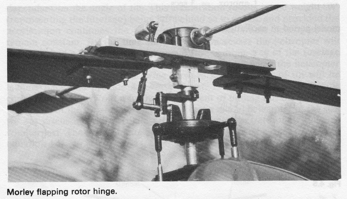
For 1975 it was further modified with a 'flapping' fixed pitch rotor head with rotor diameter now 47 inch (1194 mm).
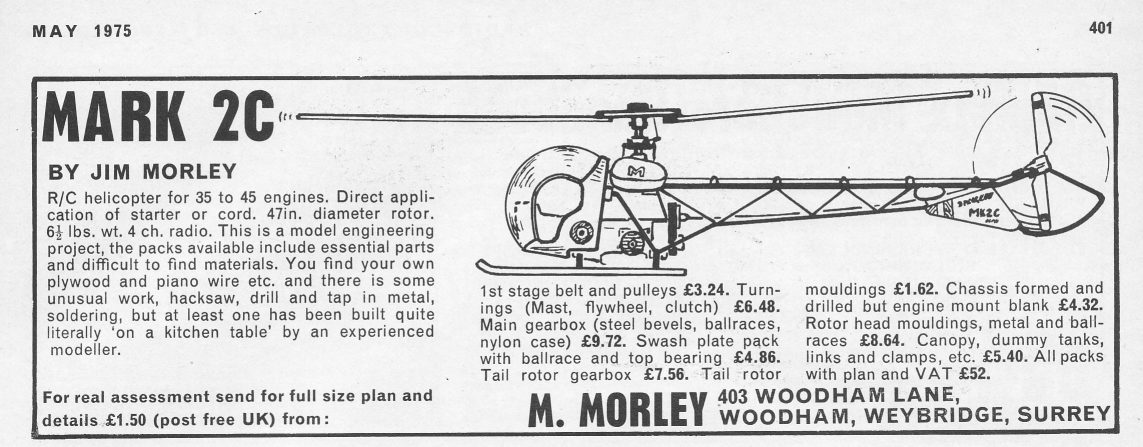 May 75 2C advert.
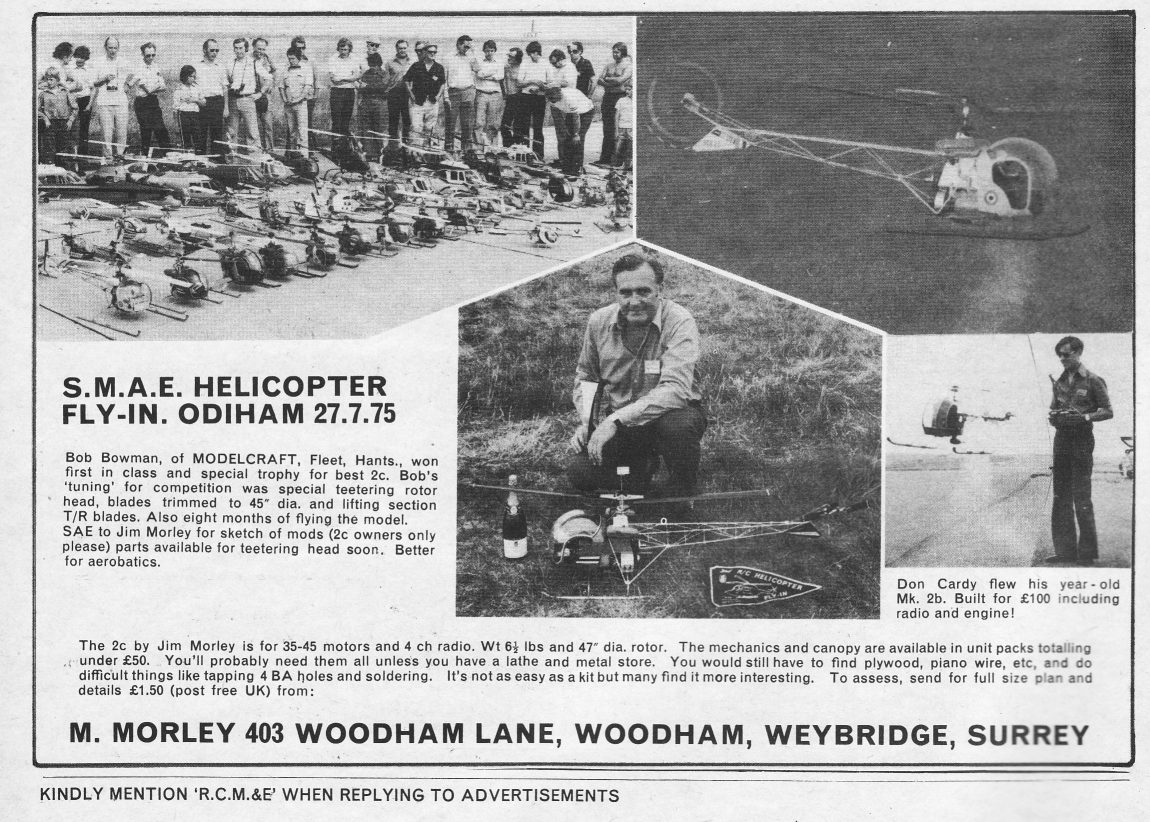 Odiham 1975.
 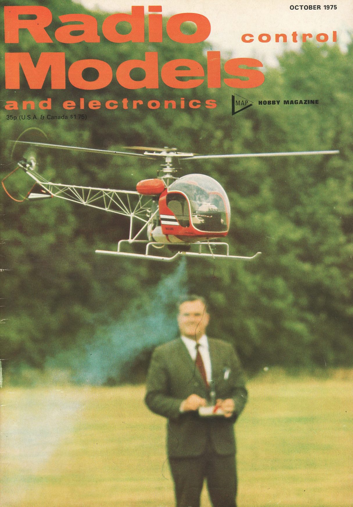 Magazine cover with Odiham winning model.
|
|
|
|
|
|
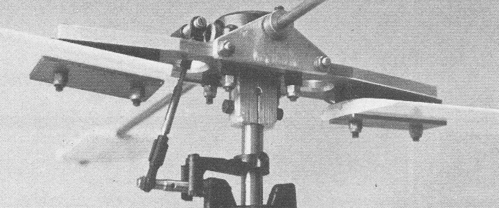
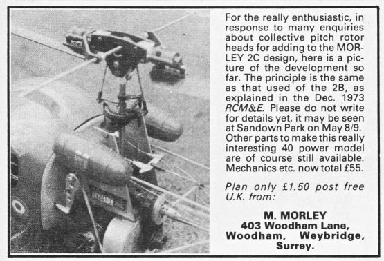

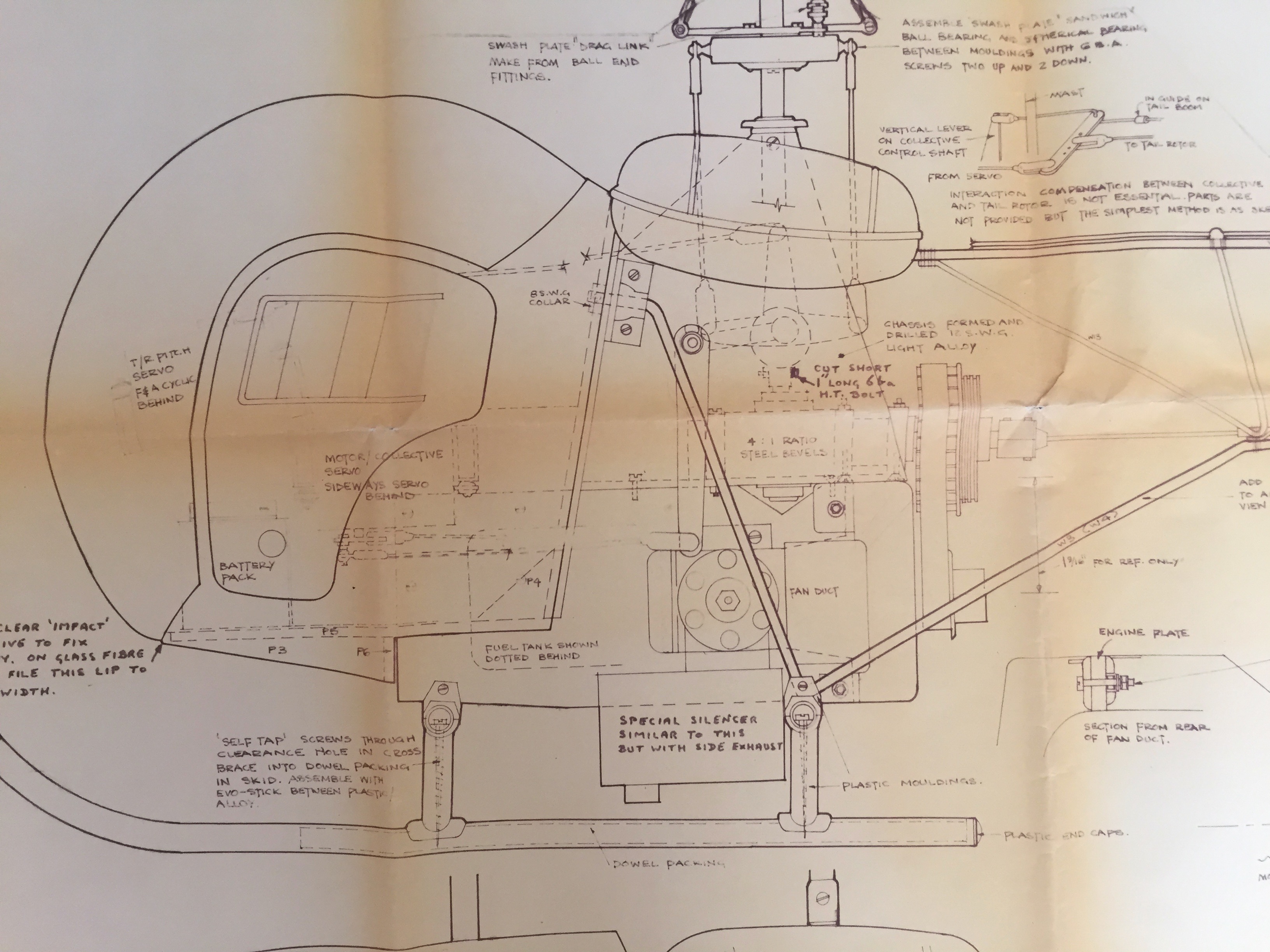
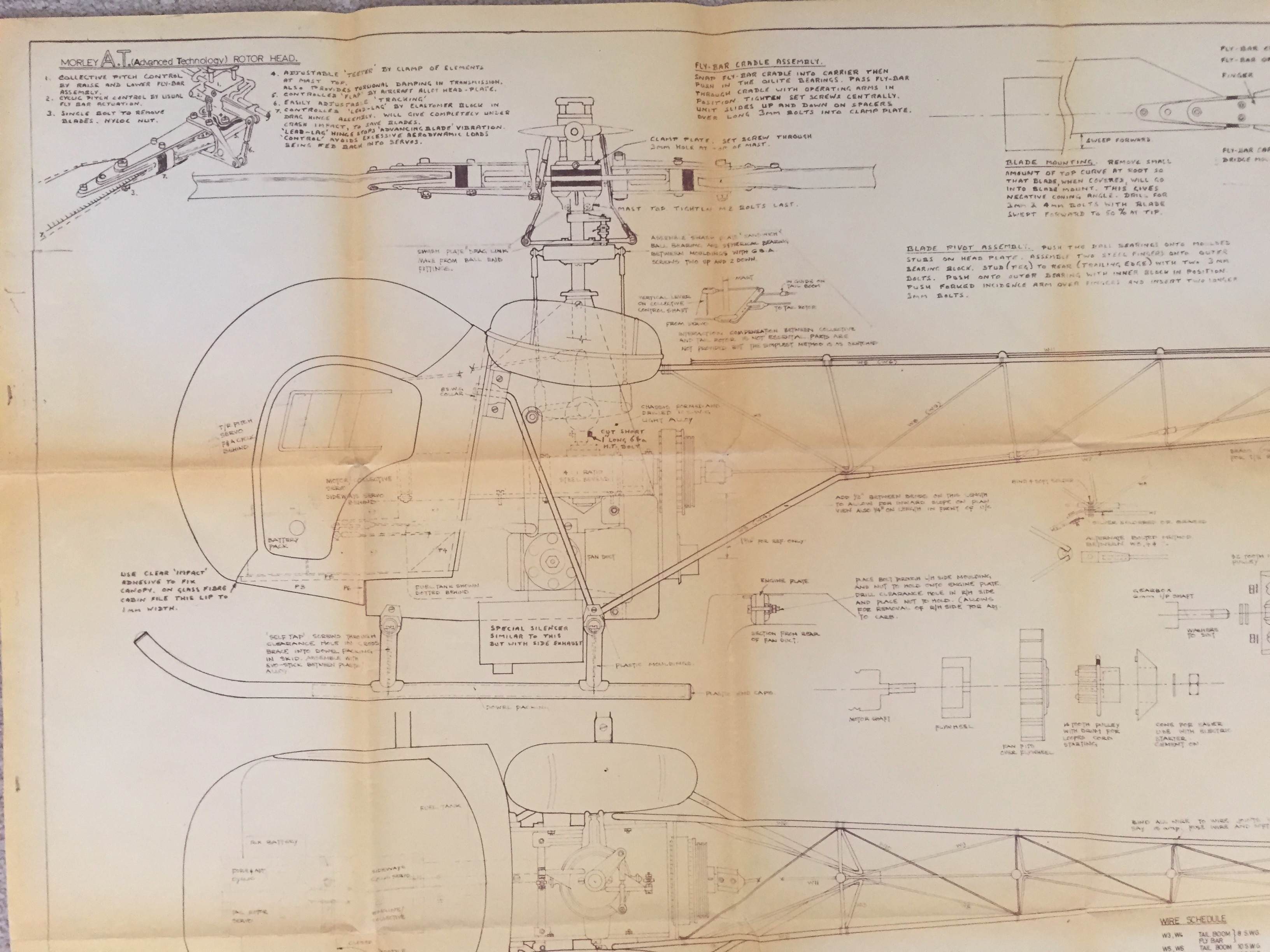
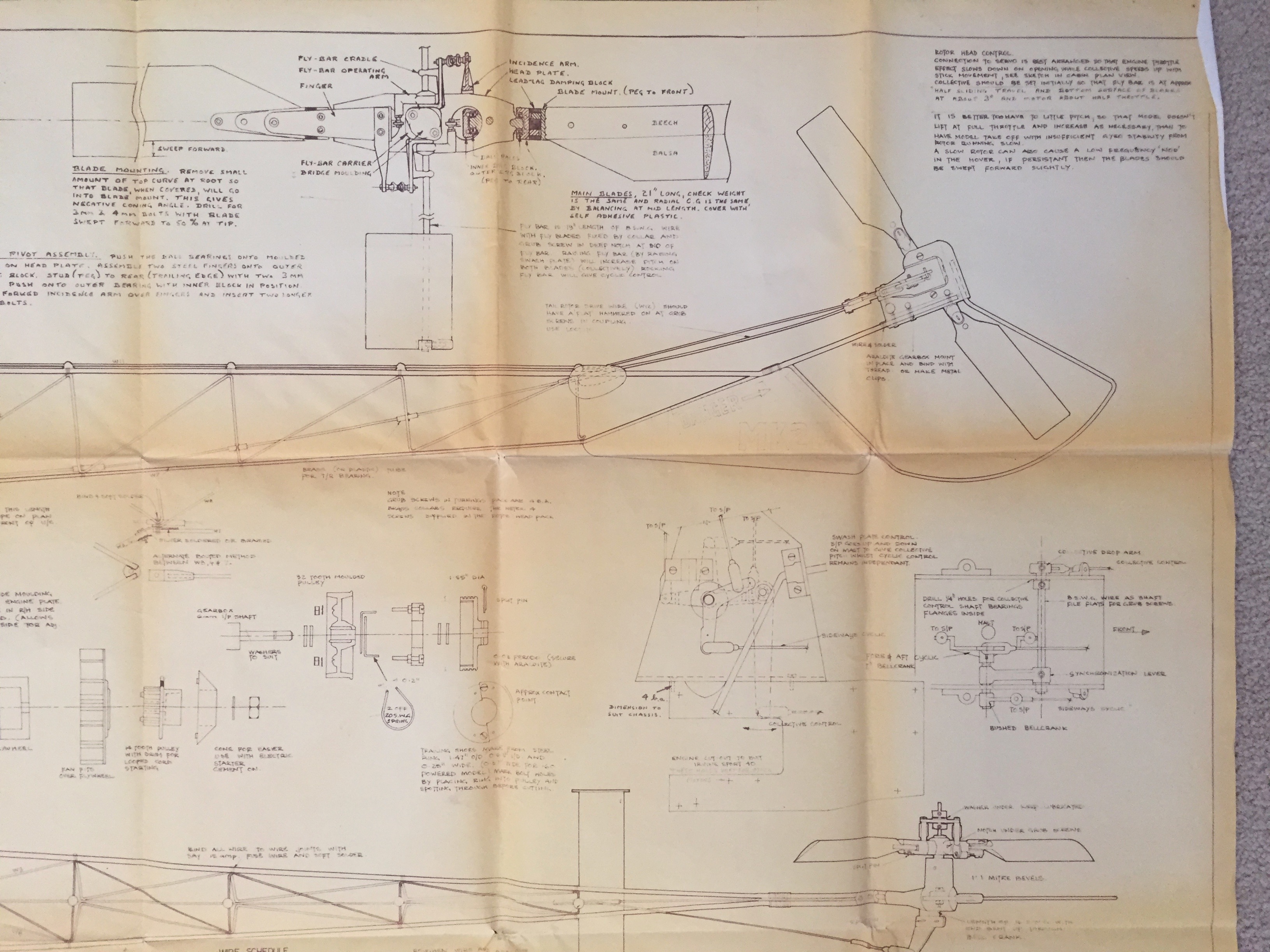
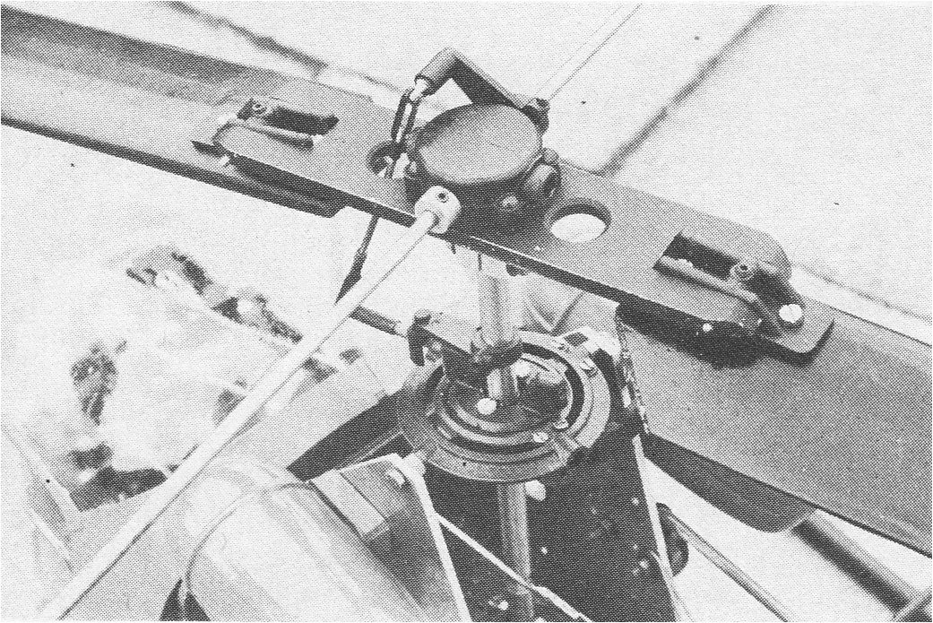
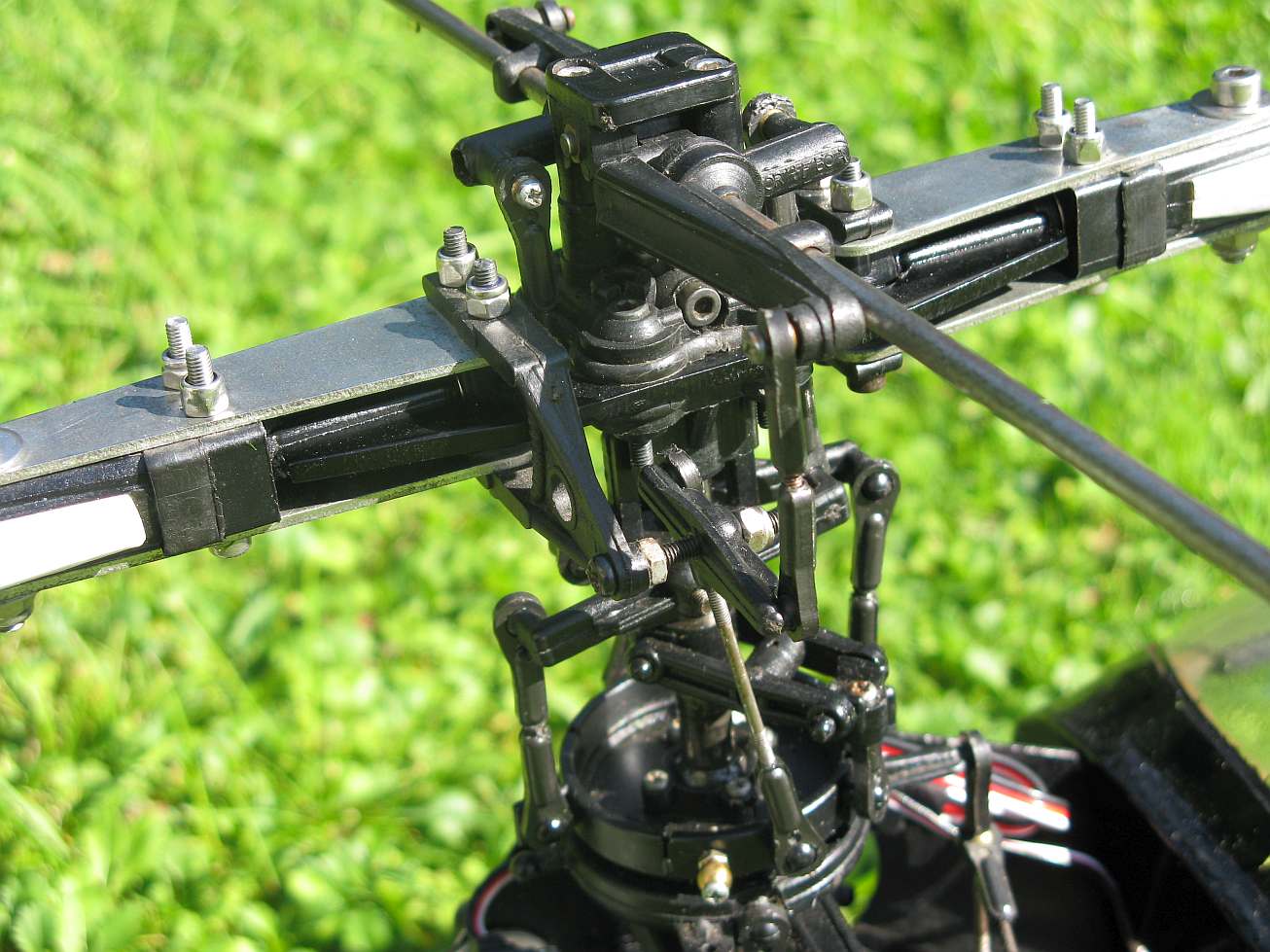
An updated version of his original design with a 'rising' flybar to impart the collective control to the main blades; raised by linkages from the swashplate which in turn was lifted by a 'cradle' assembly for the cyclic control levers.
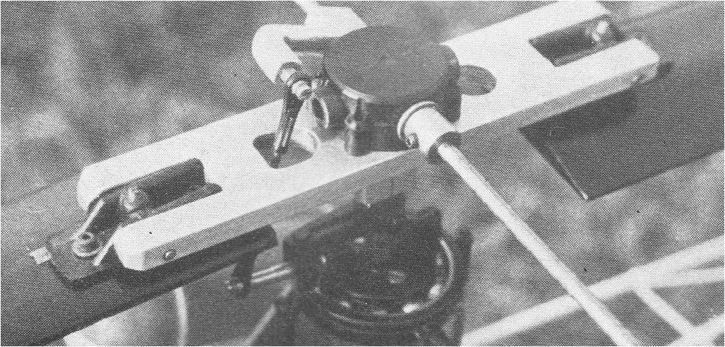

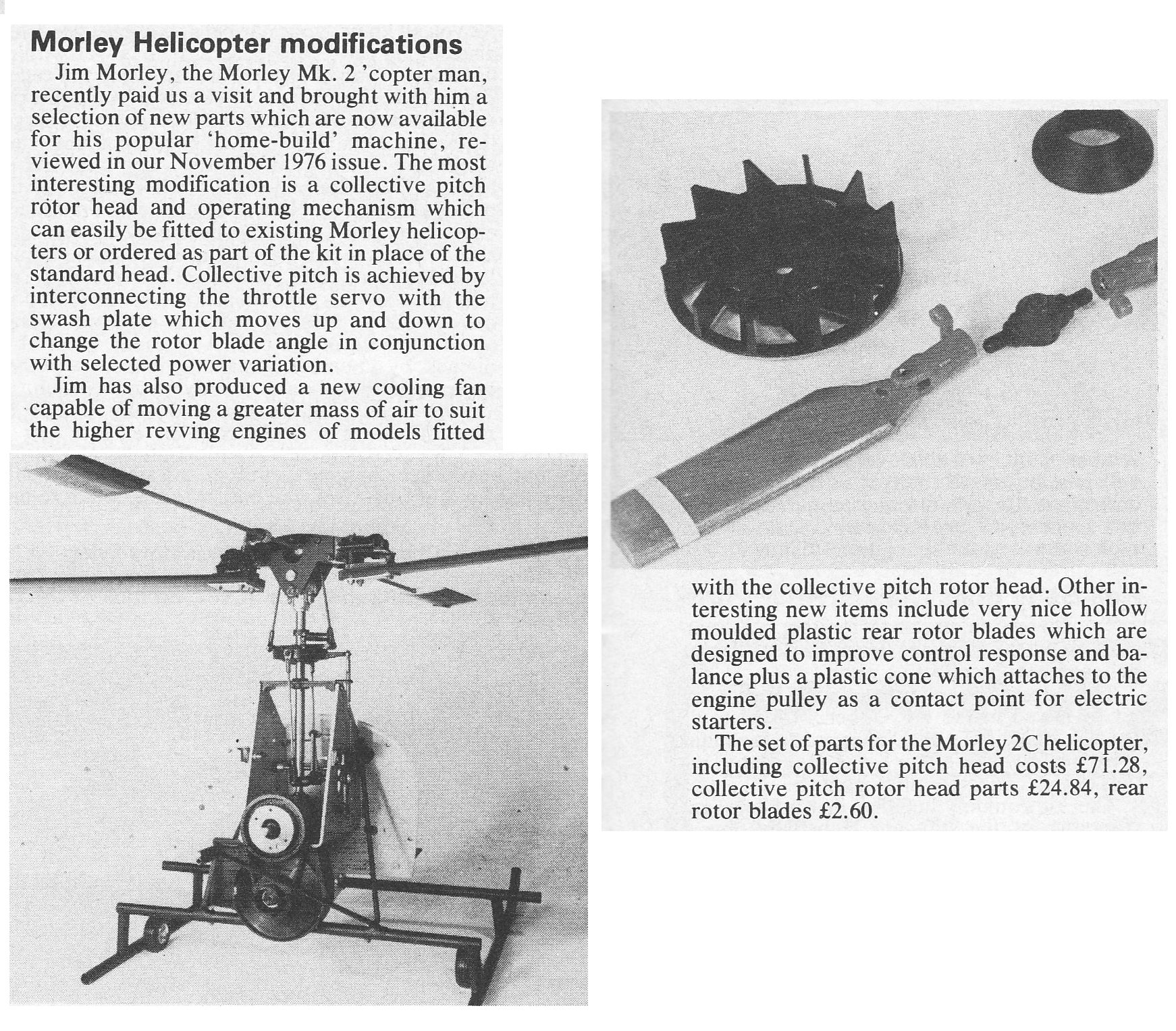

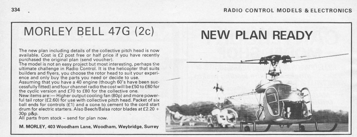
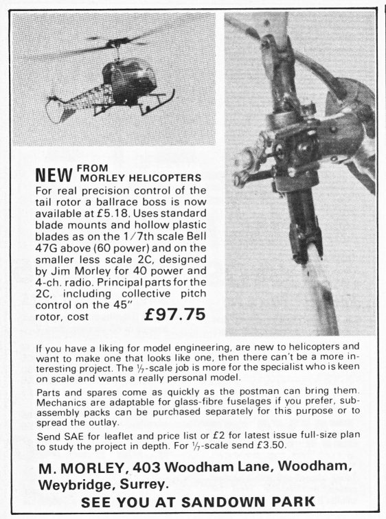
The 2C mechanics set had now been developed into a very versatile system giving a choice of three heads; fixed pitch - flapping for beginners, fixed pitch - teetering for intermediate and collective pitch for expert. The gearbox had also been uprated and could now take the power of engines up to sixty size and was suitable for developing OD models.

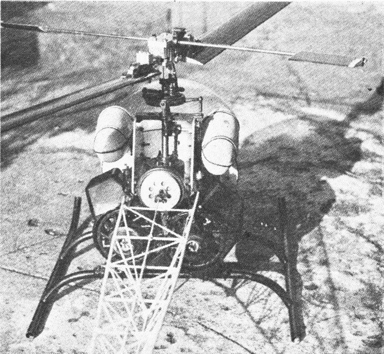
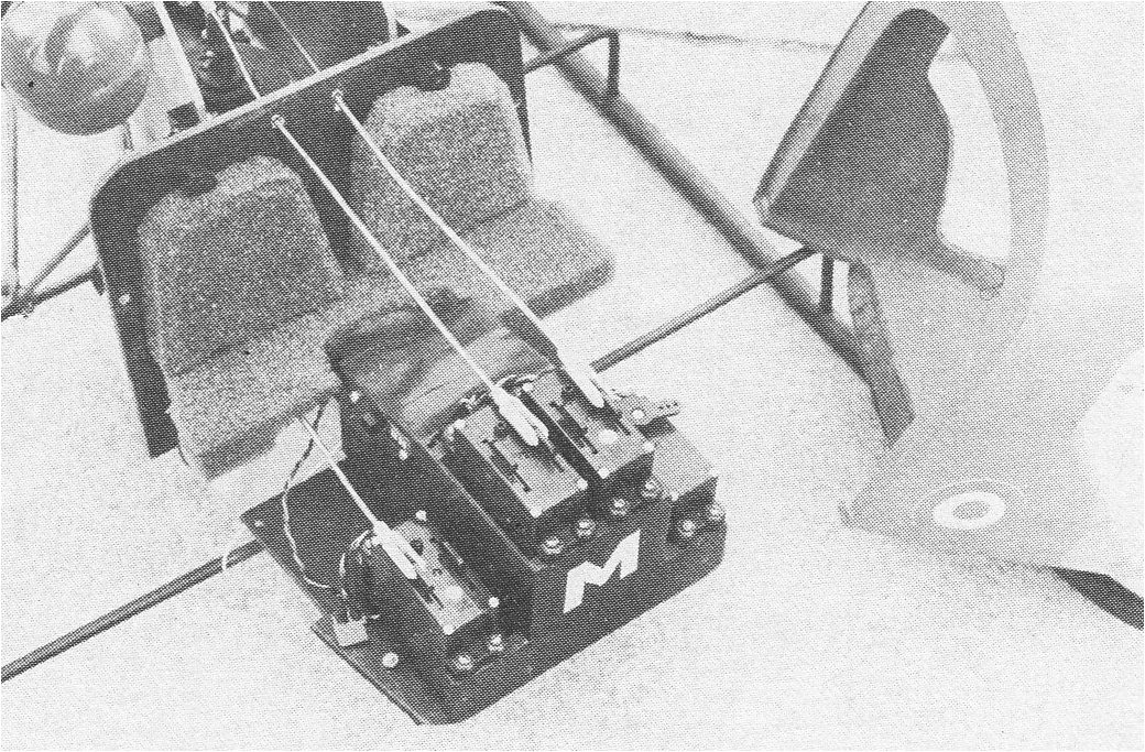
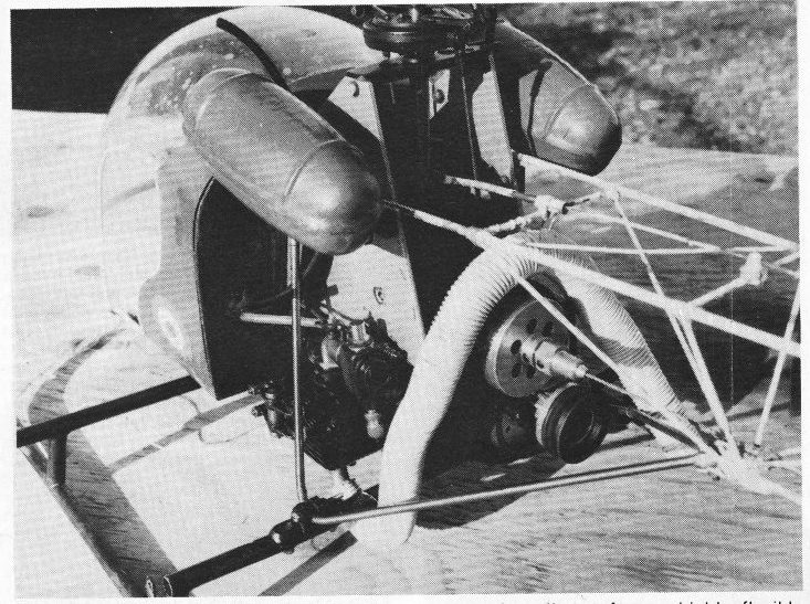
This model was fitted with two 19 size engines in a Vee formation driving through belts and a common clutch. Unfortunately this meant that you had to start both engines together using a double glow lead and if one engine 'flamed' out, the drag was enough to stop the other engine. In addition, to tune an engine required removing the others drive belt which was very inconvenient and made it quite a complicated affair to set up and tune. Despite the inconvenience of this arrangement the model did fly well though NOT considered as commercially viable.
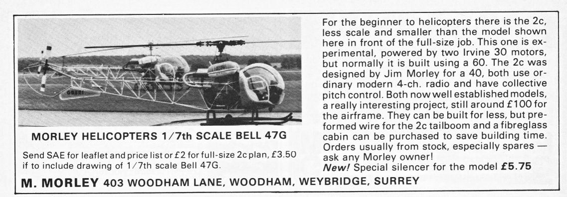
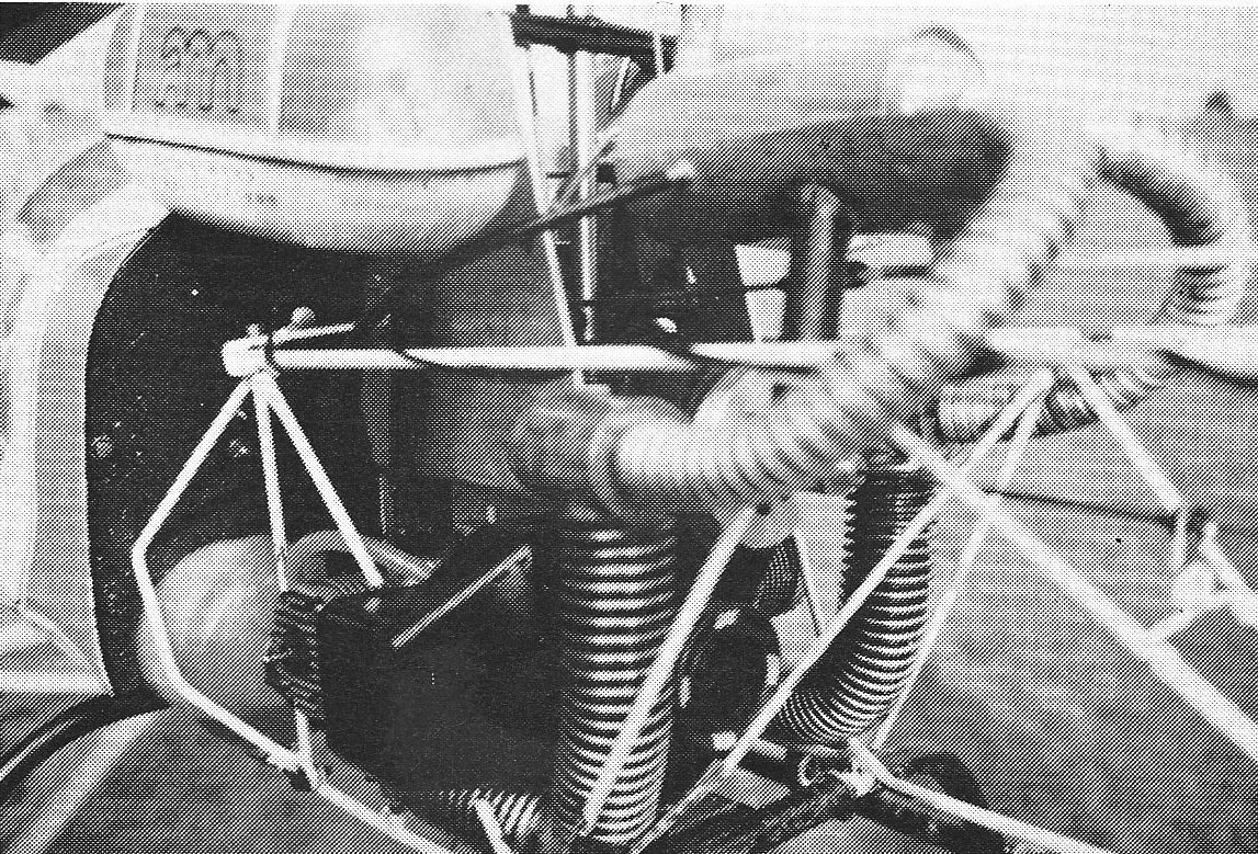
Jim considered the original twin 19 arrangement to be a bit 'Heath Robinson' and decided to make his next twin Bell 47G using the larger 1/7th scale version and this time with two Irvine 30 motors and twin clutches as per the Sea King.
 1/7th scale petrol engine 1982 |
Further development of Jim's 1/7th scale Bell 47 and this time incorporating the Magnum petrol engine; detail here - Hovering About.
 The new Morley collective head now available and this head was to become the standard fitment for the full kits that followed in 1982. |
 Brochure 1982 Brochure 1982 |


Morley Bell 47G Mk3 (1985)
 |
Specification:
|
||||||||||||||
| Documents: | |||||||||||||||
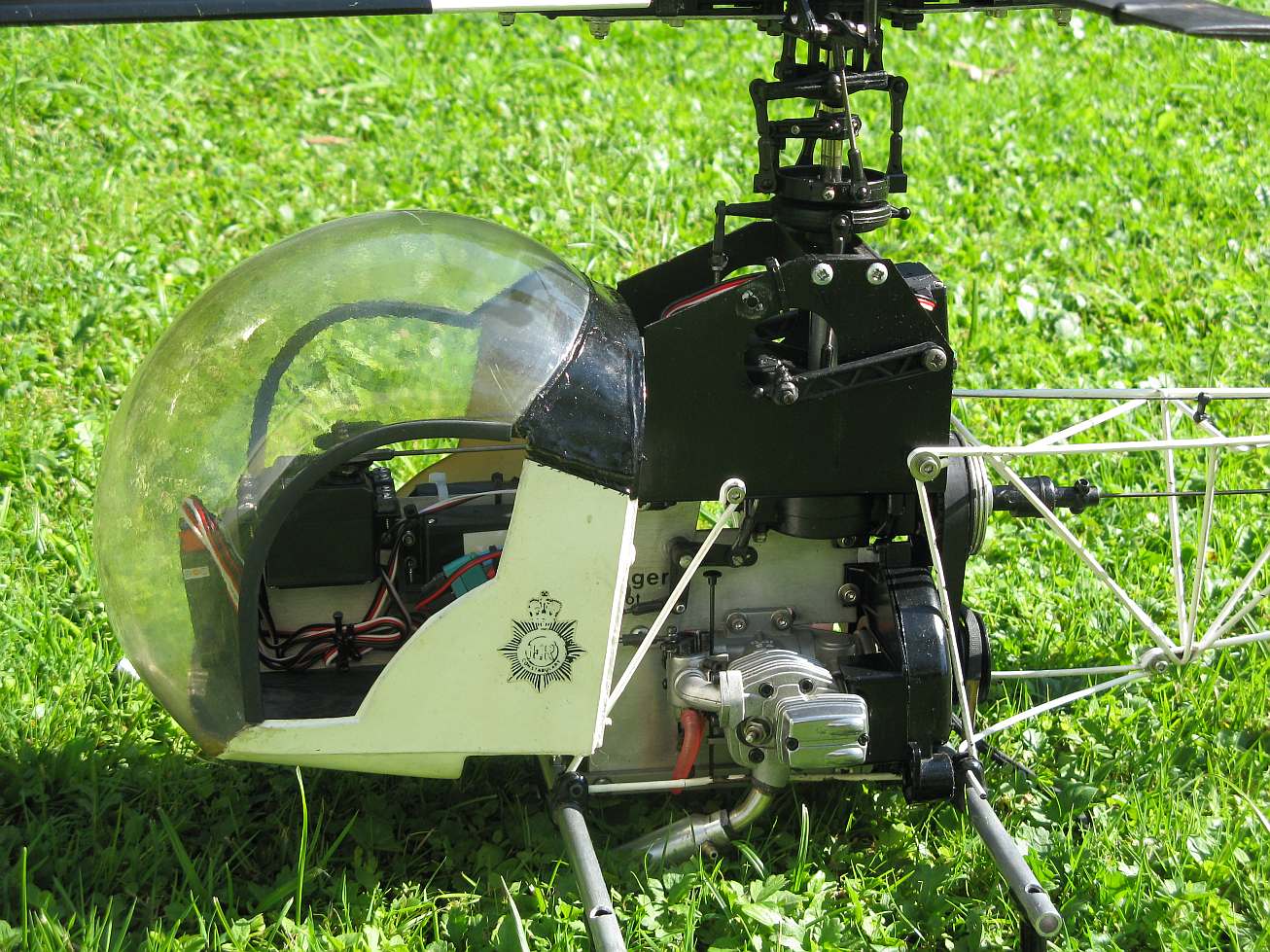
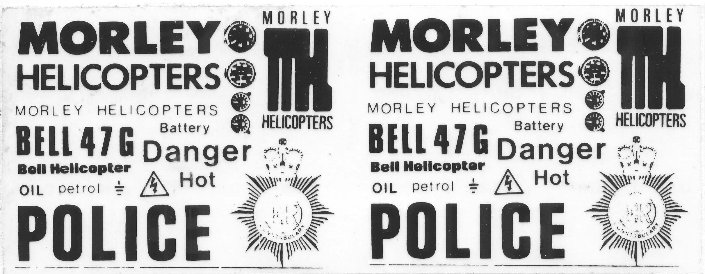 Decals for police version Bell 47G |
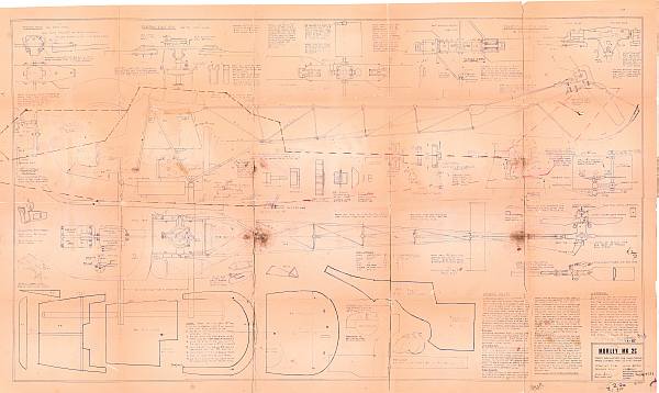
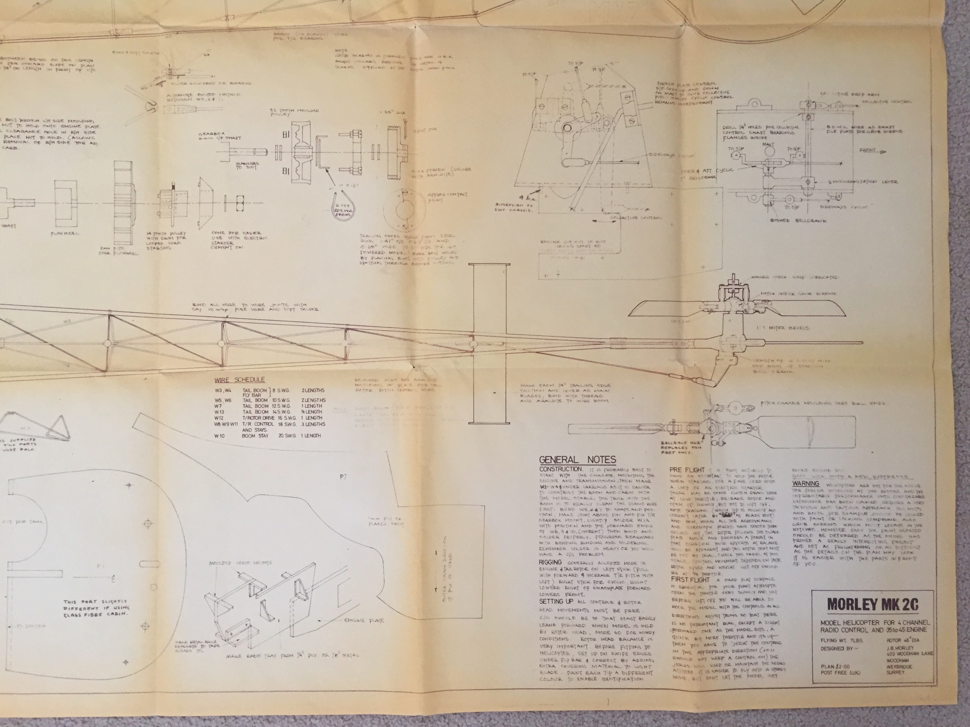
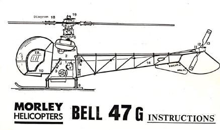 Morley Bell 47G build Manual (early edition) - Early 'hand' drawn build manual. |
Morley Bell 47G build Manual (late edition) - Later professionally produced build manual. |
|||||||||||||
| Reports: | |||||||||||||||
 Morley Bell 47G review - June 1986 Build and flying review by Jim Davey from RCMW |
|
||||||||||||||
Development continued originally with a view to being kitted along with the scale components for the Bell 47 and known as the 2D however, as the Mk3 head was available it was decided to produce the full kit under its proper scale name of Bell 47G.


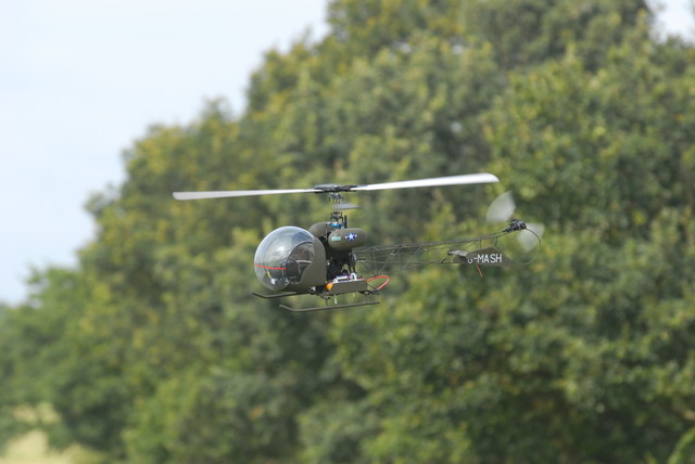
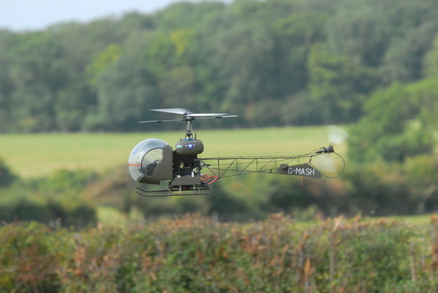
Bell 47 MK3 with 4-stroke OS-FS48

 Dave Payne's Bell 47's (Hirobo rotor head)
Photos of Jim's twin engine Bell 47G at 1/7th scale from Tish.


