The kit - The drive unit - Assembly - Installation - Flying - Conclusion - Specification - Up-date
Having seen several of the Ikarus 'Shock Flyer' series at local indoor R/C meetings, I was impressed by the performance and copied some of the more obvious features on my own 'Nextra, notably the horizontal profile and external profile spats. My own model lacked some of the flying qualities of the Ikarus series, mainly because of their flat wing compared to the cambered wing on the 'Nextra.
There was only one thing for it - buy a Shock Flyer and see just how good they were. You can buy just the airframe kit or a complete kit with a geared 300 size motor (probably a 'timed' Speed 300) and propeller. I had a GWS dual motor IPSD unit which was doing nothing so I decided to use that and bought just the airframe.
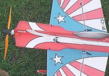
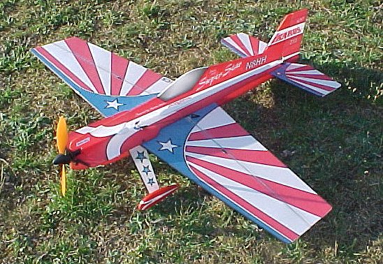
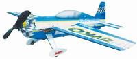
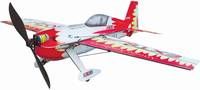
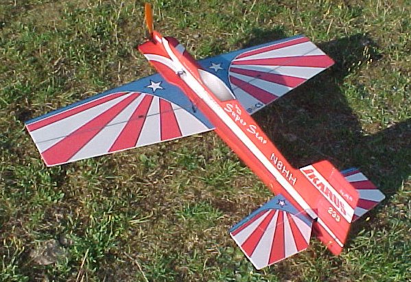
There are actually 6 kits available, comprising three different models with or without motor. I bought the 'Super Star' model. The other two available are the 'Edge 540' and the 'Extra 330' (below).
The tube of glue is barely big enough for the job and you can't afford to be generous. It is actually a contact adhesive, like GWS glue and will take a while to 'go off' if used like normal glue. To be fair, the manual does point out that this glue can be used in two ways and specifies the places where it should be used in each way. Small amounts of epoxy and cyano are also needed (not supplied).
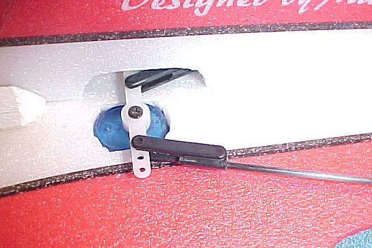
The plastic mouldings include all of the necessary parts for the control linkages. The control horns include the pushrod ends as a part of the moulding, with a thin flexible link between the two. The pushrod fitting clamps around the rod with a screw so that it is adjustable. The servo end of the pushrod also fits around the rod but is cyanoed in place. This is a conventional clevis which fits the servo arm.
The front end of the fuselage is supported by a cross-shaped plastic moulding which incorporates a mounting point for the geared motor, if supplied. If you are using your own choice of motor, you can make any provision that you like simply by leaving off the plastic moulding and trimming the rest to suite.
After separating the ailerons, the first job is to join the wing at the centreline. This is clearly necessary so that the wing will fit in the box, but so much of the wing is cut away around the centre (most of it unecessarily) that a one-piece wing wouldn't be any stronger. You then add the carbon spars at the leading and trailing edges and reinforce with the tape supplied. This appears to be of a vynyl base and is probably much better than sellotape, although it tends to look exactly the same when applied. I did experiment with Magic Tape and found that it allowed the colour to show through but rather palely. The problem with the tape supplied, from my viewpoint, is that it is very glossy - in stark contrast to the rest of the model - and shows up every imperfection. The instructions also advise using the tape to strengthen the edge of the fuselage, but I left that off for reasons that will become clear.
At this point, you have a wing which is very stiff as far as spanwise bending is concerned, but very floppy in all other directions and easy to twist.
The next move is to assemble the wing with parts of the fuselage on the edge of the bench. This is so that you can get the wing and both horizontal and vertical parts of the fuselage all at 90 degrees to each other. You then add the struts between the fuselage and the trailing edge. This locks things at 90 degrees and ensures that the wing is flat - well, along the trailing edge anyway.
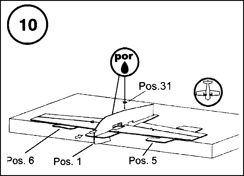
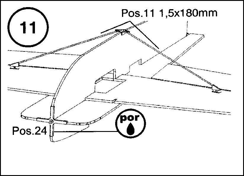
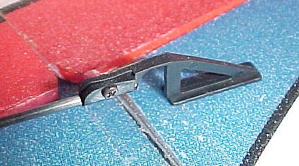
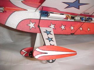
I decided to add the undercarriage struts at this point as it gave some support to the leading edge and helped to keep the wing flat. The struts pass through a rubber grommet at the fuselage side and extend up to the junction of the wing and the horizontal fuselage profile. Depron fairings are added to the legs and the instructions tell you to epoxy these to the fuselage. I did this, but I think they would be better left free. A plastic moulding is cyano'd to the bottom of the strut and this includes a socket for the fairing and a stub axle. This axle actually fits inside the true axle which is glued to the inside of the spat. The spat consists of two thicknesses of depron with an advert printed on the outer face. I glued the spat together with the ad inside as I intended to use a different sticker. In fact, it occured to me that it would be much better if the spats were painted to match the fuselage (see later).
The rest of the assembly followed the instructions. A certain amount of trimming needed to be done before some of the fuselage parts would fit snugly and there were a number of areas where the colour scheme didn't line up properly, which is annoying.
Two lengths of 1/4" triangle section balsa are provided to stiffen the rear fuselage. These are glued at the joint between the vertical and horizontal fuselage profiles to form a fillet. They do absolutely nothing to increase the stiffness and might as well be left off. I intend to try a larger depron fillet on this model, and my 'Nextra, to see if this will be better.
All those unpainted edges on the model really began to irritate me. More or less by accident, I discovered that Humbrol 'Matt Crimson' acrylic paint was an exact match and used this to paint the fuselage edges and the spats. Much more satisfying!
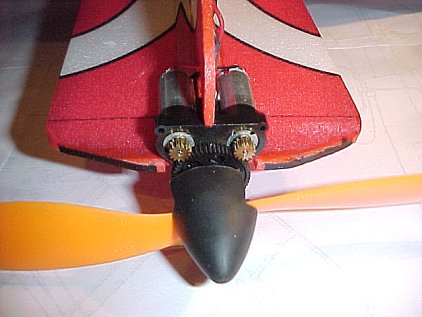
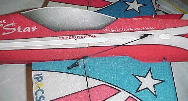
Everything else was done as the instructions and I used three Hitec 'HS-50' servos, a GWS 'R4P reciever (with external full-sized crystal which improves performance) and a Jeti '050' ESC (since replaced by a Jeti '006').
All up weight with two Kokam 640 mAh cells came to 184 grams (6.5 ounces).
That said, the first flight was anticlimatic. The model simply goes where you point it. Prolonged knife-edge flight is easy and there is virtually no control interaction. Snap rolls tend to decay rapidly after the first reaction and you can see the airframe bending way out of shape. Another characteristic is that the ailerons become increasingly sensitive as the speed drops, making landing approaches very erratic. I put this down to the fact that the ailerons tend to 'blow back' at speed due to the flrxibility in the airframe.
One solution here is to use exponential. I've never liked expo and I feel that this type of model should be flyable with a simple transmitter anyway. Going down to the local park with a lightweight (and fairly cheap) model and an expensive transmitter in an aluminium case seems somehow counterproductive.
Back to the flying. Knife edge loops, falling leafs, tight rolling circles are all there, though I've yet to manage a 'death spiral'. Despite my misgivings, the spats and fairings are still in place, though I've had to reglue one fairing to the fuselage to correct the wheel alignment.
And then, of course, there is prop-hanging. My previous efforts with my other models have had limited success. I now realise that this manoeuvre requires a long moment arm and lots of side area. It then becomes fairly easy. My choice of power makes this fairly marginal, since it needs close to full power. A throttle stick in the middle of it's range is easier to handle. Nonetheless, I can get around 3 minutes of 'hanging' from a 14 minute flight.
I did experiment with props quite a lot (all GWS). An 8 x 4.3 gave very long flights but poor performance in a breeze and it wouldn't prop hang. A 9 x 7 gave good performance and hanging but short flights. A 10 x 4.7 gave excellent hanging and very short flights. The recommended 8 x 6 seems to give the best all-round compromise (OK, so GWS do know their products best) and produced the above figures.
Maybe I should stress here that I restrict this manoeuvre to outdoor flying. I feel that people who prop hang at crowded indoor meeting are at least antisocial and verging on the irresponsibly dangerous.
I've already said that this type of model is a culture shock. It's also an excellent way of reviving an aging modellers imterest in the hobby. One down side, from my point of view, is that I also enjoy building models - but you can't have everything.
| Model | 'Super Star' Shock Flyer |
| Manufacturer | Ikarus Modellbau |
| UK Importer | J Perkins Distribution Ltd., Northdown Business Park, Ashford Road, Lenham, Kent. ME17 2DL. UK
Telephone 0044 (0)1622 854 300 Fax 0044 (0)1622 854 301 |
| Span | 31.5 in (800 mm) |
| Overall Length | 30.1 in (765 mm) |
| Weight (without battery) | 5.43 oz (154 g) with GWS R4P Rx, 3 x Hitec HS-50 & Jeti 006 ESC |
| All up weight | 6.5 oz (184 g) with 2 x Kokam 640 mAh |
| Control requirements | 3 servos and ESC |
| Drive Unit | Various (GWS 8 x 6 used) |
| Propeller | Various (GWS 4.1:1 IPSD used) |
| Battery | Various (2 x Kokam 640 mAh used) |
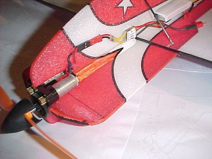
Construction and installation were straightforward apart from some relocation of items to get the CG in the right place, the motor being much lighter at just 20g. I also had to buy a matching ESC and chose a Castle Creations 'Phoenix 10'. The performance is dramatically improved, with the ability to climb out of sight in a matter of seconds (well, my eyes aren't what they used to be). All-up weight with 2 x 340mAh Kokam cells is 160g.
Unfortunately, the Kokams are wilting under the strain of a 5.3 amp current draw. I plan to try 1100mAh cells, although this will add another 30g to the weight.
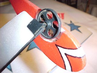
The motor includes an integral prop saver which looks a little untidy. I cleaned up the nose by gluing a short piece of 3mm carbon rod into the front of the prop and pushing a GWS spinner onto it.