The kit - Assembly - The manual - Installation - Setting up - Flying - Conclusions - Specification
The original robbe/Schiuter 'Moskito' kit appeared well over a year ago and was reviewed in the January 1994 issue of 'Model Helicopter World' by Jon Tanner. At that time, the model was supplied wit both skids and a tricycle undercarriage, together with a plastic cabin/canopy unit with an integral dummy pilot. A notable feature was the possibility of building the machine for clockwise or anti-clockwise main rotor direction. This kit is still available as the 'Moskito Standard'.
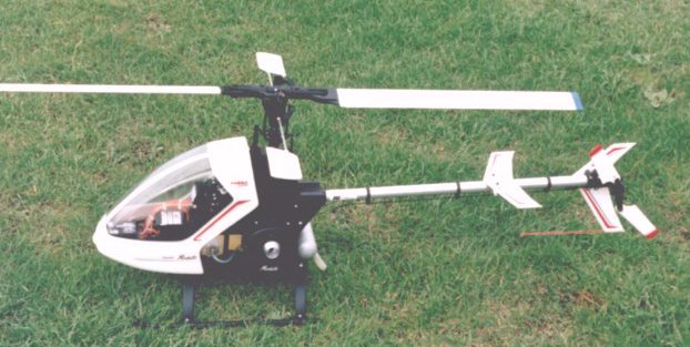
Since then, some considerable development has resulted in two more versions - the 'Basic" and the 'Expert' - becoming available. This review will concentrate on te 'Basic' version, which is somewhat smaller (main rotor diameter is 105 cm) than the 'Standard' version, being intended for 0.25 to 0.40 cu.in. motors (4.8 to 6.5cc). The machine has been considerably lightened by the use of a two-part plastic canopy, plastic skids (the wheeled undercarriage is not supplied) and smaller, lighter main blades. The swashplate mixer/washout unit has also been re-engineered.
The facility to build the model for either direction of rotation has been retained, but no autorotation freewheel is included, as the model is specifically aimed at the novice. For this reason also, if necessary, the model has been designed to use four servos with an aircraft type radio, rather than the usual five servo set-up with a helicopter radio.
The model is available as a 'package' deal with an MDS '40' motor, at a very reasonable price, so it was decided to use this motor for the review. An alrcraft type silencer is supplied with the motor and can be used with the 'Moskito' if necessary. However, a purpose-designed silencer is available from robbe/Schluter UK and it was decided to use one of these for the review.
Packaging is fairly conventional with a cardboard tray which has cut-outs to accomodate the main chassis mouldings, the canopy and the fan shroud. Another cut-out retains a cardboard box which contains the main blades. All of the other components are in plastic bags which are stowed under the main tray. The bags are numbered to match numbered sections in the instruction manual in what has become a familiar pattern.
There are two main chassis mouldings, upper and lower, which are split horizontally on a line which passes roughly through the motors crankshaft. The lower moulding accomodates the undercarriage, tank, receiver and battery pack, while the upper moulding carries te motor and gearing, mainshaft, tailboom, servos and linkages.
The motor is mounted inverted with the crankshaft running transversely across the chassis. Some considerable ingenuity has been used in the design of the motor mounts, which are almost infinitely adjustable and can accomodate virtually any mounting bolt spacing or crank length.
A fairly conventional clutch and fan assembly then drives a cross-shaft via reduction gearing. This cross-shaft carries the pulley which drives the tail rotor via a toothed belt and a bevel gear which drives the mainshaft via another larger bevel gear. The small bevel can be mounted at either end of the cross-shaft, giving the choice of main rotor direction without changing anything else.
Apart from the motor and the one-piece clutch, virtually everything so far described is in plastic. The undercarriage is all-plastic, with even the skids made from this material and retained by self-tapping screws. Both of the main chassis mouldings are quite complex and the whole assembly is rigid and quite light - and a pain to clean!
A light aluminium tailboom locates in a socket at the rear of the upper chassis moulding, with a pinch bolt to secure it. The tail box (not 'gearbox' as there are no gears) is then assembled around the rear end of the boom. It does seem odd that a lightweight, and relatively fragile, fin then needs no less than four 3mm shouldered cap head bolts to hold it onto the box.
Both horizontal and vertical tails consist of a plastic 'skeleton', which is covered with adhesive film. The main blades are the usual composite wooden construction with adhesive covering. Finished weight is 64 grammes per blade.
Both rotor heads are all-plastic with floating 'through' blade axles. The main bladeholders each have one ball-race and one thrustrace, while the tail bladeholders have two ball-races. Stopping the head with the palm of your hand needs care, as there are protruding bolt heads on the top of the bladeholders.
Let's start with that choice of rotor direction. The cross-shaft, which is driven by the motor, via the clutch and reduction gearing, has a bevel gear which drives the larger gear at the bottom of the mainshaft, as described earlier. By changing the position of the gear on the cross-shaft, the large gear can be driven in either direction. Note that the cross-shaft, which also carries the pulley that drives the belt-driven tail rotor, rotates in the same direction regardless of the main rotor direction.
This means that the tail rotor is always driven the same way, in that the lower blade moves forwards, which most authorities agree is the right way to do things. However, it is possible to turn the tail box over and have the tail rotor on either side. The manual doesn't refer to this at all, but it seems clear that the intention is that the tail rotor should be on the left-hand side and the pitch bellcrank located below the box. This is confirmed by the fact that the manual does give two suggested positions for the tail pitch mechanism relating to left or right-hand main rotor direction.
I have gone on about this at some length because - did you guess? - I decided to build the model with anticlockwise main rotor direction. When I came to fit the tail box, it seemed logical to turn the box over and have the tailrotor on the right-hand side. There is absolutely no reason why you should not do this - except that you now need a left-handed pitch bellcrank. If you leave the rotor on the left side you will need a large offset of the bellcrank to get the tail pitch in the right position - confirmed by the manual.
This is far from a good set-up, but there is an easier answer! Simply turn the tail blade holders over and have the pitch arms on the trailing edge rather than the leading edge. You can now have the bellcrank in the central position and the tail pitch will be correct for cancelling the torque. In the interests of true versatility, however, it might be better if left and right-hand tail pitch belicranks could be included in future kits.
After assembling the power unit with clutch and reduction gearing, not forgetting to fit the tail drive belt, it is fitted to the upper chassis assembly along with the mainshaft and main gear. Having fitted the undercarriage and tank to the lower chassis, the upper and lower chassis can be joined together, which traps the tank in position. You then have a compact free-standing assembly on which you can build all the mixing arms, install the servos, radio equipment, etc. before fitting the tailboom. This makes for convenient assembly and is very useful when working on the completed model, as it is possible to split the upper and lower assemblies for access.
The control system used on the 'Moskito' is a mechanical CCPM set-up which is very 'tight' and free from slop. This is dependent on the assembly to some extent as there are several places where careful tightening of bolts is required to acheive this.
I have mixed feelings about this because it is generally excellent, as with all Schiuter instructions. However, the usual layout of a common set of drawings with separate instructions in English, French and German has been changed to notes on each drawing in the three languages, which is laborious and sometimes confusing. Mixed in with all this are notes on assembly for clockwise, or anticlockwise, main rotor direction (identified by 'R' and 'L').
Notes on the rotor direction can be found elsewhere, but my feeling is that the poor novice will be lost in terms that he doesn't understand. It would, surely, have been better to give instructions for one direction of rotation and then give further comments for those who have a reason to build it the other way. The novice won't have any set ideas anyway, so let him decide later. Better still, don't let him decide at all!
The detail sketches are excellent and tell you far more than the instructions do. However, some guidance on servo arm length and servo direction would be helpful. With a modern computer radio, and experience, this is no problem but, once again, pity the novice.
One exception to this is in the situation where only four servos are used and one servo is used to operate both the throttle and collective functions. Here the instructions are quite explicit, including the lengths of the alternative pushrods (compared with a five servo set-up) and the direction and angular throw of the servo arm (but still no indication of the arm length).
It's worth pointing out that anyone who has built a model helicopter before will find that the instructions are excellent. However, as the kit is supposed to be aimed at the novice, I feel that they could be improved in some areas.
The fitting of the servos and linkages is well detailed in the instructions and there is some choice of positions for the gyro, receiver and battery pack. There is a purpose designed mounting point for the gyro behind the main shaft and there is also ample space at the front of the model. We tried the rear mounting position originally but found it easier to obtain a reasonable C of G position with the gyro mounted at the front. There are two built-in mounting points for the a gyro control box (one each side) and two possible on/off switch mounting positions.
Both chassis members are liberally peppered with holes, which makes it fairly easy to arrange reasonably direct routes for all the wiring, although it is a little fiddly to mount the larger on/off switches in the intended place.
With both a1200mAh battery and the receiver mounted as far forward as possible and the gyro mounted behind the receiver, the C of G came out just in front of the shaft. Further forward would have been desireable.
Having tried the four servo option to see how practical this would be, we eventually opted for the five servo layout to simplify setting up. With four servos, a lot of fiddling with the collective throw would have been necessary. We're just spoilt by modern radios!
Two wooden blocks are supplied as an aid to setting up. These are placed below the swashplate and serve to hold it level and at a preset height. The links to the main blades are then adjusted until the blades are set at 5 degrees positive pitch. A simple pitch gauge is included for setting this.
This set-up works well, but the actual pitch range tends to be far too great and needs to be reduced by either changing the length of the servo arm or by adjusting the radio, where this is possible.
While adjusting the pitch, we managedto break off one of the balls from the inner section of the swashplate. OK, we're clumsy, but only the fingers were being used at the time!
First attempts to start the motor were very encouraging. It burst into life at the first turn of the starter, and slowly petered out. The second attempt, with a little more throttle, produced the same result with a much longer run. In fact, it didn't run again until te next day, after spinning the clutch off four times!
I refitted the clutch with Loctite '242' and left it overnight, hoping that it would take care of things. The threadlock supplied in the kit is fine for all the usual jobs, but something a little stronger is needed on the clutch. Let's be fair here and point out that we are talking about a brand-new, un-run, motor which is mounted inverted. The inverted layout is fine, but it needs a motor with which you are familiar and which is run-in and well set-up. I deliberately retained the plug which was supplied with the motor (an idle-bar type of unknown heat rating). My whole intent here was to duplicate what might happen to someone who was totally new to helicopters.
The next attempt didn't prove to be too successful either and I managed to spin the clutch off yet again. The reason for this was a combination of factors (it usually is!). Not having run the motor, I had to guess the correct amount of throttle opening at the lower end and had it below the point where the trim could correct matters. The only way to start the motor like this was to advance the throttle stick a little, which is far too coarse a control to set the starting point of a new motor.
This alone would have been surmountable, except that both the idle and main needles were far too rich. I eventually got the motor running by screwing the idle needle in as far as it would possibly go before it interfered with the carburettor closing. The main needle ended up at less than one turn open. Fitting the ubiquitus Enya 'No.3' plug also improved matters a lot. However, the motor still needs a fair amount of throttle applied before it will start.
With the settings now somewhere near correct, the clutch throwing habit has dis- appeared. It could be regarded as a form of failsafe, since it does prevent you from doing any serious damage to the motor. The clutch itself simply unscrews until it hits the fan shroud. All you then need to do is to undo four screws to remove the shroud and then retighten the clutch.
A fair amount of ball-link movement was required to get the blades into track. The difference in lengths of the swashplate to blade mixing arm links is visually quite noticeable and can only be due to differences in the roots of the main blades. The model runs with a marked coning angle on the main blades, which could be reduced by running at a higher RPM. However, the model soon lets you know that it is not happy at high head speeds, when the collective response becomes rather twitchy.
Having assembled the machine as per the manual, without recourse to extensive balancing methods and using just the basic pitch gauge supplied, the model flew without any real changes being required and with a commendable absense of vibration. However, the overall collective range was far too great and needed reducing at both high and low points. See 'Setting Up'.
Because of the relatively small rotor discand the low centre of gravity position, the model is very stable. One notable point is that it will lift off dead straight without any cyclic inputs being necessary. The actual handling is intriguing as any cyclic input moves the head to one side and then the fuselage moves underneath it. Large inputs can move the head quite quickiy and give the impression that it is very responsive. However, the model itself stays more or less where it is, and just waves the head around!
It is not a part of this review to investi-gate just how easy it is to initiate a boom strike, but I think it could be quite difficult. From the point of view of the novice, this might be more important than anything! Oris it? Shortlyafterwriting the above, I found myself in exactly the situation which frequently results in a boom strike! The model came back towards me in the hover for no apparent reason and I had no choice but to 'dump' it onto the ground. This broke off the lower part of the fin, which did its job in protecting the tail rotor. The main blades did not contact the ground, despite which there were several broken parts.
The main item damaged was yet another ball broken off the swashplate. This did not fail at the obvious weak point, but broke off right up against the swashplate, leaving a hole in the rotating portion. Both blade holder pitch arms were broken, and both ball links were broken off the blade mixing arms. Any one of these, or half a dozen other things, could have been responsible for the actual incident but, collectively, this is a lot of damage for what amounts to a heavy landing! None of the shafts, or the flybar, were bent and the blades were unmarked.
If we concentrate on the premise that the 'Moskito Basic' is aimed at the novice, then it acheives that aim extremely well. The layout of tall shaft, low centre of gravity and short ligh tblades means that it is very stable and is not prone to the usual problem that besets the beginner - boom strikes. The undercarriage layout also means that a training undercarriage, while still advisable, is not really essential.
The only real criticisms we have are that the instructions could be improved from the point of view of the novice and it would be better to use the existing fin from the 'Moskito Standard', which is solid, rather than hollow. If the intention of the hollow fin is to save weight, it would be more effective to leave out one of the bolts holding the tail box halves together (there are no less than seven!).
| Product | 'Moskito Basic' |
| Manufacturer | robbe GmbH Modelsport, Postfach 1108, D-36352, Grebenhain, Germany. |
| UK Importer: | robbe/Schluter UK, Dick Wallinger Models, 51 Sapcote Road, Burbage, Hinckley. LE10 2AS. Tel: 01455 637762. |
| Main Rotor Diameter | 41.34 in (1050 mm) |
| Length | 39 in (990 mm) |
| Tail Rotor Diameter | 9.85 in (250 mm) |
| Main gear ratio | 7.7:1 |
| Main to tail gear ratio | 1:4 |
| Weight | 6lb 14oz. (3.12 Kg) |
| Powerplant | 0.25 - 0.40 cu. in. (4.8 - 6.5 cc) two-stroke glowplug engine |
| Control Requirements | 4 or 5 servos and a gyro |

![]()
![]()
![]()
![]()
![]()
![]()
![]()