The model - The kit - Assembly - Radio installation and set-up - Flying - Options - Conclusions - Specification
The 'Maverick' first appeared at the 1990 Sandown show in un-named and incomplete, .60 powered, experimental form and drew some favourable comment. A feature of the model was the use of a mechanical CCPM system in which all three of the pitch servos rose and fell with the swashplate. At that time, Jim Morley's company was going through some extensive reorganisation which meant that there was no finance available to develop the model further.
A little later, I was invited down to Jim's home workshop to view one of the flying prototypes which was being used to try various types of rotor head. This was still .60 powered, but Jim explained that his intention was to introduce the model initially as a .50 powered machine with a possible later upgrade to a .60 size.
The model was duly introduced as the 'Maverick' at this years Sandown show, gained favourable comment from some surprising sources, and seemed to be a natural for review in this first edition of a new magazine.
Intended for 0.45 to 0.53 sized engines, the 'Maverick' has two stage reduction gearing with the tail rotor drive being taken from the idler shaft between the two stages via 90 degree bevel gears. The motor shaft points vertically upwards and is fitted with a fairly conventional clutch with a pinion which drives a gear on the idler shaft. This shaft then travels the full depth of the mechanics to drive another pinion at the base, which in turn drives a gear fitted to the autorotation unit at the bottom of the main shaft. Both sets of gears have adjustable mesh, with the final set having enough adjustment to allow for the fitting of different pinions to change the ratio. In standard form, the overall ratio is 9.4 to 1 and the tail rotor runs at 4.16 times the speed of the main rotor.
Some development of the CCPM system has led to the collective servo being moved to one end of a 'see-saw', with the two cyclic servos mounted at the other end. This produces a balanced system, which reduces the load on the collective servo. The complete unit is fitted below and, slightly behind, the swashplate. Throttle and rudder servos are fitted above this unit and on the outside of the upper side frames. As a result, all of the servos are close together and there is space for the receiver, or a small gyro, immediately below them. Several possible variations exist for the disposal of the remainder of the radio equipment.
There are several notable features of the design. One is an almost complete absence of bellcranks (there is one on the tail gearbox), which means that all linkages are straight and direct. Another is the use of brass 'pull-sert' fixings in many locations on the chassis. These are a form of threaded bush which are pre-fitted and remove the need for separate nuts which can easily be lost. A familiar Morley feature is that the tail control wire is fitted inside the tailboom.
It is clear that the model has been designed with versatility in mind. For instance, the standard set-up is to use a side exhaust motor with the custom made Morley silencer, but it would be very practical to use a rear exhaust motor with a 'dustbin' silencer mounted below it. There are several possible tank locations, the kit being supplied with a custom moulded unit which fits close to the C of G.
The cabin consists of two ABS mouldings and a separate PVC windscreen. A third ABS moulding serves as a combined instrument panel and front mounting point. When assembled, it is fitted to the chassis via four rubber grommets and needs nothing more to hold it in place. Tail feathers are nylon mouldings and are in a white finish which matches the main cabin mouldings.
A feature of the very robust main rotor head is a large 'head button' (other manufacturers please copy!). The flybar now follows convention with the paddles threaded on to a fairly soft material (as one who has had paddles move in the air, I rather liked the old Morley system with the paddles solidly locked onto a piano wire flybar). Again following convention, the head has a 'through' feathering spindle, although custom made conical rubber inserts are used instead of simple 'O' rings, which allows the damping to be adjusted by packing. Specially produced offset ball links are used for connecting the mixer (sometimes called the 'washout' unit) to the swashplate which avoids unsightly (and doubtful) bent wire links.
My kit arrived via the post, and 'Parcel Force' had done a superb job of rounding off the corners and turning the straight edges into twisty bits! They also left it on my doorstep in pouring rain. Despite this, everything inside was unscathed and dry - full marks for packaging!
All of the various sub-assemblies are packed in clearly labelled polythene bags. Each different size of bolt or screw is packed in a separate bag, ie. 'M2 Fastener Pack', 'M3 Fastener Pack', etc. These are then packed in the main box, using the cabin halves as separators, along with 'bubble wrap' material. A cardboard separator incloses the windscreen (thoughtfully wrapped in tissue), which has the tank and front cabin mounting stowed inside it.
The tail boom runs diagonally across the box and the main blades (composite wood with lead weights and 'fablon' type covering) are tucked along one side. Undercarriage components and the various wire parts are disposed among these items using the bubble wrap as a separator.
This is all covered by an inner lid, of stout card, which has the chassis and main mechanical components laid out on it and covered with shrinkwrap material. When you first open the box, you are greeted by this impressive array. All of these components are identified by an asterisk (*) in the instructions so that you don't waste time looking in the various bags for them.
Instructions come in the form of two books, one with the text and another with the diagrams, together with a separate sheet listing all the available spares and prices. Finally, there are two sheets of vinyl stickers. One has blue and green trim, while the other has blue and yellow.
What do you need in addition to the kit?
To complete the model, the following items are required:
1. Helicopter motor of .45 to .53 cu in capacity.
2. Helicopter radio with 5 servos.
3. Tail rotor gyro.
4. Suitable silencer.
Before the model can be flown, you will also require a starter motor and suitable battery, with charger, a glowplug battery and clip, again with charger, some glow plug fuel and a means of transferring it into the models tank (pump or 'squeeze bottle').
The SC and ASP motor ranges are specifically recommended, while the ST, OS and Webra (and other) motors can be used with small modifications to the fan and/or propnut, all of which can be done and/or supplied by Morley.
Some wheeling and dealing by the editor led to an SC .46 being supplied for the review. Unfortunately, this was an 'aero' engine, as a 'heli' version was not available at that time. While the instructions led one to believe that the SC engine was a direct fit to the model, it was necessary to extend the slotted mounting holes downward to allow the motor to be mounted in the correct position. It was also necessary to modify the throttle arm in order to rotate it into the correct position for proper operation. A 'heli' version of this motor is now available which has an extended, and adjustable, throttle arm. The extension means that the throttle linkage will need to be outside the chassis of the model, which is much less neat.
The radio used for the review was my JR 'PCM 10' with 5 NE 517 servos which were perfectly satisfactory. Having said that, anyone who intends to indulge in '3D' flying would probably be advised to fit a more powerful (spelt e-x-p-e-n-s-i-v-e) servo on the pitch channel.
A Quest 'Custom' gyro was used since I had one available. A Morley gyro would have been more appropriate, but my 'Competitor' gyro is doing such a good job in another model that I was loath to disturb it.
Morley produce a semi-tuned silencer specifically for this model and one of these was supplied with the kit. With the motor used, it was necessary to remove a small portion of the mounting flange to clear the throttle arm - not necessary with the 'heli' motor. It (the silencer) works extremely well but represents a very large unsupported load hanging on the motors exhaust stack. Although there are many 'Maverick' models out there which appear to be working satisfactorily with this arrangement, I was unhappy about the fatigue life and added a tinplate strap to support the weight of the silencer. This is purely 'belt and braces' to ease my natural paranoia!
There would be little point in covering the complete assembly in detail, so I will only describe any points that were not completely straightforward.
I followed the assembly sequence outlined in the instructions apart from the fact that I did not have the motor available at the time that I started, so I could not assemble the clutch until later. The only small problem here was that the hole in the centre of the fan was slightly larger than the crankshaft, so it was necessary to 'eyeball' the alignment. A washer is supplied to be fitted here, but this is smaller than the recess in the fan, while the original propwasher is larger. Don't use 5 minute epoxy to fit the clutch lining, use thick 'UFO' or 'Stabilit Express'.
When assembling the tail drive take off ('tail transfer gearing'), you start by fitting a ballrace onto the take-off shaft. The above mentioned card lid has a ballrace right next to the shaft concerned and it took me some time to discover that it was the wrong one! There is no identification mark on the card to identify each item. This is not a real problem, but there are a lot of separate ballraces involved and I found it necessary to use the part number to refer to the spares list to find the size that I needed, and then use a ruler to identify them. An easy solution would be a page in the instructions with a diagram of the card, identifying each item.
The take-off gear on the first stage drive shaft is pre-fitted to a splined section of the shaft. In my case, these splines extended well below the gear and rubbed against the plastic case. A sharp blade was used to slightly enlarge the hole at this point (it is only there to retain grease).
I was unable to find any self tapping screws in the kit which were large enough to attach the front radio tray to the side members (nor does the spares list mention any), so I found some suitable ones from my own stock.
The swashplate comes pre-assembled and it is only necessary to fit the outer balls for connection to the servo links. However, I did find that two of the inner balls were loose, due to the nuts not being fully tightened against the balls before fitting, so I advise that you check this carefully.
Pay special care to the assembly of the main rotor head and the disposition of the two different conical washers employed. No mention is made of the direction of rotation, or which side the pitch arms are fitted, although this can be deduced from the diagrams. Note that the head rotates anticlockwise when viewed from above and that the pitch arms are on the leading edges of the blades. Make sure that the paddles are also fitted for anticlockwise rotation.
Again, on the tail rotor, while mention is made of the fact that the tail rotor rotates clockwise, it does not say which side we are viewing from, and it does not specify which side the pitch input is. This is further complicated by the fact that the tail blade holders have a pitch arm on each side. So, clockwise viewed from the outer end of the output shaft and pitch input on the leading edge. When attempting to balance the tail rotor assembly, one blade was considerably heavier than the other and needed a lot of material removed to make it balance. I then remembered that I had another set of these blades which had been supplied as an upgrade for the 'Huey' review, but never used. These proved to be spot on. This is purely a matter of luck with moulded components, of course, but it pays to check.
Both of the above paragraphs may appear to be nitpicking and I would agree, except that I have seen novices produce some weird and wonderful arrangements on models that I would have thought could only be assembled one way!
No mention is made of attaching the various tubes and spacers which go inside the boom to the boom itself, but this is essential to prevent the unit from 'floating' along the boom. This could produce problems, particularly as the assembly is not symmetrical.
Joining the two halves of the cabin is fairly easy, but don't be tempted to trim away too much material beforehand. I trimmed away the flange in the instrument panel area and then had some trouble lining up the holes for the screws which help to hold the front mounting point in position. I then had to find a way of filling the unsightly gap which I had left. My fault entirely! If you are allergic to cyano, you can use one of the liquid polystyrene cements ('Mekpak', 'Liquid Poly', etc.), This welds the material beautifully, but takes time to harden.
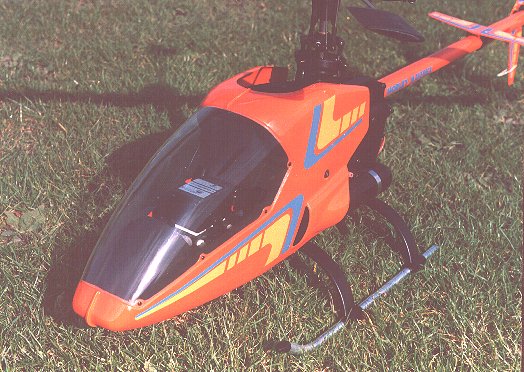
The windscreen is inscribed with an outline which is intended to help you to trim it to size. In my case it was very obvious that this was well inside the correct position. Initially, I trimmed away the absolute minimum amount of material to give undistorted edges and this was very nearly the correct size. Examine the box illustration carefully and you will note that there is a gap between the rear of the screen and the cabin. I have yet to see a 'Maverick' without one.
My one deviation from the specified way of doing things relates to the main blade covering. Contrary to popular belief, we have had some pretty hot weather in the last couple of years and I have had to recover all of the blades that I have with self-adhesive type covering, due to the appearance of ugly blisters. Yes, maybe I do keep my models too long, but I much prefer heatshrink blade covering. The shape of the latest type of Morley blades lends itself admirably to this and the result is most attractive. Incidentally, the manual advises that the lead weights should be fitted with slow setting epoxy, of which I heartily approve. I can think of at least one 5 minute epoxy which never goes really hard and is subject to 'creep'. When finished, the blades weighed 110 grams each.
I also extended the fan shroud with clear plastic so that it covered the motors cylinder head, a la Schluter. As the shroud finishes well above the motor, this seemed to be an obvious modification.
A couple of points did strike me as odd. One is that the outer end of the tail drive wire has a push-in coupling, whereas the front has a coupling which is attached to the wire via grubscrews (no less than four - well done). If this situation were the other way round it would be possible to remove the complete boom and tail for transport. The other point is that the vertical fin is very thin and flexible, yet is held on by four 3 mm set screws. I must confess that I did feel that the fin was rather insubstantial, but this has produced no problems whatever to date.
I have a general aversion to model helicopters which have a white base colour and I wanted to identify mine in a crowd (there's a lot of them about - 'Mavericks, not crowds), so I decided that I must paint it. Orange seemed to be a good choice, since it would go with either of the trim sheets (although I would never use green on a model). Originally, I had hoped to get a car spraying friend to spray it with isocyanate (fuelproof) paint as used for plastic bumpers on cars. Unfortunately, pressure of work on his part meant that I had to recover it from him after all he had done was to take the shine off the surfaces with a 'Scotchbrite' pad. I had thought that 'sticky' primer would be needed on the nylon tail surfaces, but took a chance and sprayed them with 'Duplicolor' (sic) followed by fuelproofing with 'Aerocoat'. Surprisingly, this is still in place, with no cracks or peeling.
I suppose I should quibble about the fact that the manual only describes a Mode 2 installation, but you try buying a Mode 1 helicopter set on this enlightened island of ours! Apparently, after taking years to convince the Japanese that these strange foreigners actually wanted to fly their helicopters on Mode 2, they now think that we are all like that!
As already described, the servos are all accommodated in a tight group. Apart from the tail control wire, all of the linkages are supplied already assembled and of approximately the right length. Several options are available regarding the disposition of the remaining items. From the point of view of the connecting wiring, the best location for the receiver is below the servos. However, a really neat installation would require the servo leads to be shortened and there is no ideal location for the aerial.
I opted for this layout initially, with the aerial going from the receiver to one rear undercarriage strut, then across to the opposite strut and the remainder going back to the fin. The gyro and battery were mounted at the front, which meant that there were four sets of wires running the length of the chassis. In this situation, some 3 to 4 ounces of nose weight were required to get the centre of gravity on the mainshaft and there was a fair amount of fuel spray making its way onto the connections to the receiver. The receiver also protruded slightly from the rear, which I did not like.
While I was waiting for a heatsink head to fit to the motor, I decided to change this arrangement and to fit the receiver at the front. Instead of using extension leads, I extended the servo leads as necessary. Although there were now 7 sets of leads running the length of the model, it was possible to make a fairly neat installation with the aid of the nylon tie-wraps supplied with the kit, and the aerial could be run in a more or less straight line from front to rear. 2 ounces of nose weight were required in this configuration.
Some care is needed to ensure that the wiring to the moving servos is properly supported. This can be done by tying it to the servo cradle with the tie-wraps provided. Similar care is needed where the wiring passes between the tank and the main gear.
One of the tank supports incorporates a mounting for a switch and a remote glowplug connector. While there was no problem in fitting a 'phono' socket for the glow plug, the switch plate would not accommodate the smallest JR switch. It did, however, take the JR charge socket. I extended the plate, with the aid of a stand-off bolt from the rear side plate and was able to fit both the charge socket and the switch.
As is becoming standard practice, I set the linkages so that the pitch servo, see-saw, swashplate and mixer were all in the middle of their available travel and then set the main blades to zero pitch. This gives the maximum flexibility in setting up. The available pitch range is well in excess of 10 degrees each way. The manual recommends +4 at mid-stick and this was used as a starting point.
When finished, I had four small self-tapping screws left over. These were perfect for attaching the undercarriage struts to the skids. The manual makes no mention of this, but it is a good idea as the skids are a loose fit in the struts.
All-up weight with the equipment specified, a 1000 mAh battery and two ounces of nose weight is 8 pound 12 ounces.
After setting up the motor in my usual manner by running the model without the rotor head fitted - much safer, much easier to check the servos for proper operation and sensitivity to vibration, and you would have to be stone deaf to over-rev the motor - I immediately found that there was very little movement of cooling air past the motor, no more than a gentle breeze in fact.
After fitting the head and main blades and attempting to fly, I also found that rather more than 4 degrees of pitch was needed. Some time was then spent adding pitch and throttle in order to persuade the motor to slow down, and the model to leave the ground. Eventually, I had the model in a high-revving hover at the mid-point on the throttle stick - and a maximum endurance of about 3 minutes from a cold start before the motor overheated. Obviously, a heatsink head was needed.
Later measurement of RPM and pitch and throttle settings showed that with 5 degrees of pitch and 2/3 throttle, the model was hovering at 2,000 RPM head speed!
After more work and adjustment - plus a heatsink head - the hover speed is down to 1,600 and there are no cooling problems in the hover. At this point, however, forward flight was limited to one circuit before the motor appeared to overheat. I performed several autorotations - it's the easiest way to get it down when the motor sags. As you might expect with the light blades, there is no reserve at the bottom, but no problems either. The model is very robust and appears not to be prone to boom strikes. I also managed the odd loop or roll.
This apparent overheating caused me some deep thinking (?). I had heard odd comments about similar problems, but it was very evident that there were a lot of 'Maverick' models around which performed quite happily - most of them being fitted with ST 45 motors. Plans were made to replace the SC with an ST when - quite by accident - I discovered the answer. Flying of the model had been somewhat limited pending the taking of the necessary photos for this review. With that item out of the way, I went out for my first real flying session, safe in the knowledge that I could now break it!
Some vertical climbs and circuits revealed that the motor would go 'hard' quite soon after going to full throttle. The 'circuit' part was actually a red herring, since the same thing happened in a vertical climb. Opening and closing the needle led to very little change in the situation. At this point I realised that I had never actually heard the motor run rich. On impulse, I opened the needle a full turn, expecting a very rich motor run. It was indeed a little rich in the hover, but full throttle at last gave full - and sustained - power. Eureka!
It seems that the special silencer does indeed work exactly as a tuned pipe and needs much more fuel when really 'on'. The fact that the motor continued to run in this situation is probably a tribute to it, but I would have been happier - and less confused - if it had stopped!
Using the servo arm lengths detailed in the instructions produces a nice response, but I did find it necessary to reduce the elevator throw a little to suit my own taste. There are no peculiarities at all in the handling. Some people find that they prefer one direction of main rotor rotation over the other, but I do not find this a problem. Having learned to fly on clockwise rotating machines, I have a slight preference for anticlockwise types like the 'Maverick'. Having said that, however, it much prefers being rolled to the left. Rolls to the right are very untidy - to say the least.
Several options are available for the model, with more on the way. Currently available are carbon fibre side plates and a longer boom, together with wider and/or longer main blades. Floats are also available.
All current kits have a modified tank, with a sump, and a longer tail rotor shaft, to give more tail pitch range.
It is medium sized, robust, goes together well, flies well, is cheap (and will get cheaper compared to foreign competitors), has cheap and easily available spares and it's British.
I like the direct control links, the cabin styling (some don't), the general strength (but Oh! that fin), the easy starting (no extension needed), the internal tail control, the cabin mounting and the head button. I've already mentioned the things that I don't like.
The instructions are fine for anyone who has already built a helicopter, or two, but are rather sparse for the total novice. In the diagrams, all of the parts are identified by part number only, which ties in with the text. On reflection, I think that this is a good idea, as are the separate books for text and diagrams.
An update of this review will follow in a couple of issues time, when we will deal with further flying impressions, updates, and any further developments.
Safety note: If you fly another model immediately after flying a 'Maverick', be careful. Those buttonless heads can really smart!
| Model | 'Maverick' |
| Manufacturer | Morley Helicopters Ltd., West Entrance, Fairoaks Airport, Chobham, Woking, Surrey. GU24 8HX. Tel/Fax: 01276 856292. |
| Main rotor diameter | 1330 mm (52.36 in) |
| Tail Rotor diameter | 254 mm (10 in) |
| Overall length | 1200 mm (47.25 in) |
| All-up weight (dry) | 3.97 Kg (8 lb 12 oz) |
| Engine to main gear ratio | 9.5:1 |
| Main to tail gear ratio | 1:5.5 |
| Control requirements | 5 servos and a gyro |
| Power requirements | 0.40 to 0.53 cu in glow motor |
