Now you see it, now you don't - The kit - Construction - Installation - On being green - You can't put it off any longer - Proof of the pudding - Now, take that - It's not the kits fault, mister! - Conclusions
In keeping with the fashion established by another well-known helicopter writer, I find it necessary to start off by giving my excuses for the long delay in producing this review. Basically, it amounts to being jobless, transportless and hopeless. I could have lied (who me?) and used the weather as an excuse, but it had improved well before the model was finished.
The one excuse which I do have lies in the difficulty of finding a suitable colour scheme. In fact, the full size machine has probably been decorated in just about every possible shade and hue. The difficulty lies in finding evidence of the fact. Finally, a phone conversation with Martin Briggs, of Morley Helicopters led to the suggestion that I use the one colour scheme that I had been trying desperately to avoid - olive drab.
His reasoning was that the model had already been painted in anything but the standard military colour scheme, so why not. My main reason against the idea (and everybody elses, I imagine), was the difficulty of seeing it. A little research, however, led to some interesting findings...
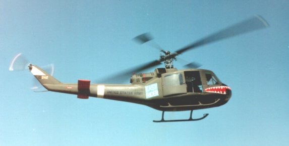
When the Bell UH-1 'Iroquois' helicopter (actually, it was originally designated HU-1 - hence the nickname 'Huey', which eventually became semi-official) first appeared in Vietnam, it carried a high gloss Olive finish. To make it easily visible if forced down it also had white bands on the roof with prominent US stars and the word 'ARMY' also in white. Strangely enough, it made a very good target and it was eventually realised that the colour scheme had something to do with this.
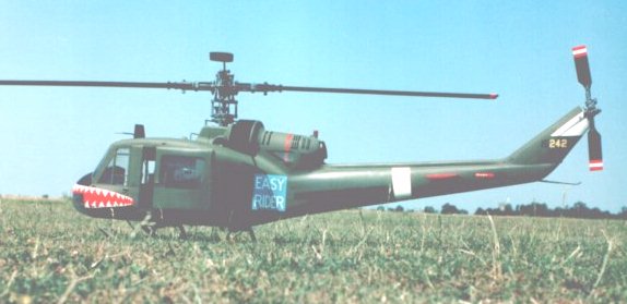
The 'cure' was to repaint the machines in a flat olive drab finish without stars and with the words 'UNITED STATES ARMY' in black! Now pilots in time of war have a habit of dressing up their transport in individual colour schemes so they immediately began to add various graffiti to make them easily identifiable!
So, paint it high gloss dark green with high visibility markings or paint it in matt dark green and then make it visible, voila! One other possibility which I considered was to model one of the prototypes which were silver all over. If you know how to produce a decent silver finish, this could be the way to go.
As with most good ideas, the basic design was stretched, widened, given extra engines and eventually developed into the civilian 212/214 series. While these later machines are, perhaps, better known in this country, the original machine has immense character and appeals to most helicopter enthusiasts.
The kit is intended to depict the UH-1B model but actually represents a hybrid between this and the UH-1C. Lots of 'B' models were updated to 'C' specification, so this is quite OK. I rather like the 'C' version, which has a filter on the engine intake and a different arrangement of aerials on the roof rather than in the nose. Note that a genuine 'C' has a noticeably larger fin, so the uprated version is easier. The 'C' also had a bigger tailplane which was larger on one side. I have been unable to find any detailed information on this.
This is definitely a kit for modellers, rather than assemblers. Many of todays helicopter kits require only an assembly job (some not even that) and appeal to the flyer, rather than the modeller. Morley kits have always been aimed at the modeller and are, to my mind, better for it. Apart from the greater satisfaction involved in producing the model, it also means that the manufacturers can continuously update and improve things almost on a day to day basis.
Designed for 40-45 size motors, the 'Huey' incorporates the well established Morley mechanics into a GRP fuselage. This is in two halves with the split being arranged around the door area. The roof is attached to the front section and the floor to the rear, which forms a convenient 'shelf' on which to mount both the mechanics and the undercarriage. A short length of plastic tube is fitted into the rear of the fuselage to form a convenient mounting for the standard tail gearbox.
A considerable amount of woodwork is involved in the completion of the fuselage and this is all of ply, supplied in die-cut sheets. The die-cutting is excellent and the parts almost fall from the sheet. Most of these parts are used in the nose section and the lazy builder could omit most of this. Some of the parts have to be bonded into the rear fuselage section to support the mechanics and these cannot be omitted.
There is a great deal of choice involved in the completion of the body, depending on just how much work the builder is prepared to undertake. For the lazy, the windows can be merely painted on and the interior work kept to a minimum. However, for those who wish to produce a more convincing and accurate scale model, a full set of transparent window mouldings is supplied and these include parts for the seats and instrument binnacle. A neat touch here is that the large side doors are also clear mouldings, which means that it is merely necessary to mask off the windows before painting.
These doors are arranged to slide and can be fixed in any position. The instructions recommend that the model should be flown with them in the open position for cooling purposes. This is entirely prototypical and many full-size machines were flown in action with them removed.
Instructions are in the form of separate sheets supplied in a plastic folder. Many of these sheets have recently been rewritten and improved with much clearer sketches. Two sheets of decals are supplied which cover not only both of the variations detailed above, but also include a host of small stencilled signs with which the full-size aircraft is adorned. These all have a matt finish but are in the form of vinyl stickers which have a glossy backing film. This is a minor inconvenience if you are modelling a machine with a matt finish and will require a coat of matt varnish.
Control of the model is effected via a moving swashplate CCPM system with mechanical mixing, for which a complete set of linkages is supplied, together with servo mounts, etc. A helicopter radio with 5 servos and a gyro is required.
The first item to be tackled is the main gearbox and engine mounting. The engine used fir the review was a Super Tigre 45 'Hele' with the standard swinging muffler. I had been told by others that it was difficult to accommodate an engine with a heatsink head, since the heatsink would foul the clutch shaft. In fact, the ST has a very narrow heatsink and it almost cleared the shaft. The solution here was to pack up one side of the engine with a piece of 1/16th inch glass PC board and trim a similar amount from the plastic engine mount on the other side. This means that the engine is slighted canted in the frame. A more serious degree of interference occurred between the heatsink and one corner of the gearbox casing. One corner of the heatsink was sawn away to rectify this.
The instructions refer to a 1mm gap at the rear face of the flywheel but do not show exactly what is meant by this. In retrospect, I believe that this means that the rear face of the flywheel should be 1mm in front of the front chassis member. I originally mounted the motor so that the rear face of the fan was as close as possible to this chassis member, in the interests of fan efficiency. It soon became clear, however, that the drive belt to the clutch would now seriously foul the front of the fan shroud. This was easily solved by inserting a 1/8th inch spacer between the flywheel and the motors prop driver. This appears to give the optimum alignment of the drive belt, but the rear of the flywheel is still inside the chassis member.
The problem here is that the further forward you move the fan, the less clearance there is to get the starting belt in through the side door. It also means that there will be a large gap between the rear of the fan and the chassis member. If cooling is a problem, it would be advisable to fill in this gap with balsa.
The swinging ST muffler allows you to obtain the best spacing and alignment so that it misses the tank (which sits on the rear of the motor mounting) and the throttle linkage. Morley produce a special silencer for the model which, unfortunately, does not fit the Super Tigre.
All of this assembly - and most of the rest of the model - is secured by cross-head screws. This is not a criticism of the kit, since I am aware that some people actually like them, but I hate the damn things! It does not matter how many different types and sizes of screwdriver I have available, I never have the one that is the correct fit on any given screw. Despite this, it all went together very well.
Unlike most models, the swashplate comes in kit form (personally, I like this). The design has recently been changed and the actual bearing surfaces are now of metal, rather than the earlier plastic. With careful assembly, this results in a free running and slop free swashplate. My particular example originally had a rather sloppy fit on the centre ball. Contacting Martin Briggs revealed the fact that this had now been changed and he sent me a replacement which was a perfect fit. Latest kits should be fine in this respect.
Another peculiarity of the review kit was that the front bearing on the clutch shaft was a free sliding fit. This is normally a force fit on the shaft which ensures the correct positioning inside the top of the fan shroud. In the instructions there is a reference to spacer washers 'if needed'. They are in fact essential to avoid the clutch rubbing against the drum and the fan shroud. The two threaded rods on which the clutch shoes pivot are about 3mm too long and need this amount removed from the rear to avoid fouling the fan shroud. Apparently, both of these points have now been corrected.
The body shell is superbly made and is about the lightest example that I have seen. It is both thin and flexible and does not suffer from cracking or chipping when worked upon. Windows were cut out using a mini drill fitted with a cutting wheel and then finished off with a fine file. A ply floor is fitted to support both the mechanics and the undercarriage and this has a narrow extension carried forwards into the nose which is intended to support the battery and the gyro.
top of the mechanics is secured to the rear fuselage by bolting to ply brackets which have to be bonded in position. This particular joint is essential to the integrity of the whole model and I would advise that some glass cloth reinforcement is added in this area. All wood to GRP joints on the review model were made with Stabilit 'Express'. As already mentioned, there is a considerable amount of woodwork in the nose of the model. This is mainly cosmetic and only needs a bare minimum of gluing. If you are weight conscious, the ply could be replaced with balsa.
The control system consists of two pivoting arms which support a cross-shaft which acts as a pivot shaft for several bellcranks. The shaft and bellcranks move up and down for collective control, taking the swashplate up and down with them. Explicit instructions are given for the assembly of the bellcranks and I would advise that you follow this exactly, taking careful note of the orientation of all bolts and the number of nuts used. Actual radio installation will be covered in the next section.
Tail gearbox assembly is straightforward. Input and output shafts have one ballrace and one bronze bush. Ensure that the bronze bushes are accurately located in the recesses designed for them. I managed to get one displaced on the first assembly and ended up with a lot of endfloat in one shaft.
The taildrive consists of a 16swg wire running in a curved brass tube. 16g is a lot of wire to bend through this sort of angle and it should be kept well lubricated. I glued a piece of brass tube into the rear of the tailboom arranged so that I could add oil to the rear end of the drive wire tube, without dismantling. The joints at each end of the wire consist of a plastic hexagonal ball and socket. These should be well greased to avoid wear.
Attachment of the undercarriage is by means of plastic saddles which are secured to the floor by bolts which pass right through and attach to nuts buried in brackets at the base of the mechanics. Skids and struts are joined by further plastic mouldings which are an excellent fit. The whole lot can be snapped together and permanently secured with either epoxy or small screws.
At this stage, the body can be completed by adding the windows. Apart from the door windows, all of the glazing on the full-size machine is fitted to the outside of the body and secured by riveted strips of aluminium. This is well simulated on the model by simply gluing the windows onto the outside of the body shell. A variety of adhesives can be used for this, but I used Evo-stik contact adhesive for convenience. All of the joints will eventually be painted over so there is no problem with fuel attacking them.
The clear mouldings are the least satisfactory part of the whole kit. They are not really clear and have a sort of frosted effect and they are all just slightly on the small side. Panel lines are moulded into the windows to represent the strips covering the edges and these tend to be rather variable with badly defined corners. In particular, the windows under the nose need great care in trimming to ensure that they will actually fit. The door windows are intended to be fitted from the inside and are moulded to fit into the window opening and give a flush effect. I found this to be far from satisfactory and made up my own from clear sheet and attached them to the inside. This allowed me to model the sliding windows in the 'down' position for an extra intake of cooling air.
Elevators are from balsa sheet and are fitted in two halves to wires which pass through the fuselage. Here again, I made up my own with a layer of 1/64th ply on the top to help resist 'dings' during handling.
Doors, seats and instrument panel were made up as per the instructions. Note that the instrument panel is not central, but offset to the right. From here, the amount of detail to be added depends on you individual perseverance, but it is advisable to model at least the rudder pedal linkages since these are clearly visible through the nose windows.
Head and blade construction is fairly straightforward following the new instructions. Several of the mouldings have recently been changed (in particular, the latest blade holders are now a better fit to the blade) and some of the original options have been eliminated which simplifies things somewhat. A couple of years or so ago, I assembled a Morley head for friend Derek Farley and upon returning the completed item was told, "Hmmm, yes, I didn't do it that way!" No such dilemma should present itself now.
As is my usual practice with kit reviews, the installation of the R/C gear was done exactly as per the instructions. It immediately became apparent that the model was going to be rather nose heavy and this allowed me to make one modification which I had already contemplated. As previously stated there is an extension of the fuselage floor into the nose to accommodate the battery and gyro. This means that an awful lot of wiring has to negotiate the area where the starting belt will be thrashing around. It also means that two, or more, extension leads will be required to connect everything.
So, I killed two birds with one stone (hope that isn't prophetic!) by moving the gyro to a platform on the rear of the mechanics which placed it behind the mainshaft and inside the dummy engine cowling. This made the wiring simpler - and more direct - and corrected the CG nicely. The battery is still located in the nose, but there is only one lot of wiring which has to pass close to the starting pulley.
Using the recommended R/C gear layout does mean that there are servos scattered all around the mechanics and the throttle linkage, in particular, is very convoluted. However, just looking at the thing, it is very difficult to devise anything better. The carburettor on the engine used does not help the situation since the throttle arm is not adjustable. I had to resort to twisting it around somewhat to allow proper actuation.
The linkage from the tail rotor servo to the tailrotor bellcrank is intended to be via a piano wire in an aluminium tube. I have never found this to be satisfactory, so I replaced it with a Sullivan snake. Yes, I should have tried the system supplied first, but changing it later would have been very difficult.
Quite specific instructions are included for the actual set-up of the control linkages, including recommended lengths. I believe that these are based on the set-up used by Jim Davey on his models. Jim and I seem to agree on most things, so it will be interesting to see if this works for me.
I have long held the view that aeroplanes, or any conveyance for that matter, should never be painted green. Indeed the motor racing world is convinced that green is unlucky and have spent a great deal of time producing paints which could be called green, but actually were something else. British Racing Green, for example, is usually nearer black - or even metallic blue/green as on BRM's. Exactly why this superstition should have arisen is not clear - perhaps I shall find out - so I eventually decided that if Kermit can make a success of singing about it, why not?
Having finally given in and decided to paint the 'Huey' to resemble a murder weapon, the question arose of just which shade it should be. The Humbrol colour chart shows several different shades which are called 'Olive Drab' and most 'Huey's' on film appear to be closer to brown! I eventually decided that colour number 155 appeared to be correct - and it is very close to brown (even now he's cheating!).
Before we go any further - yes, I did use Humbrol matt enamel to paint the beast. You may have been told by others that this is not fuelproof. In fact, it is - but not to synthetic oils. Another point which applies to both enamel and polyurethane is that they are porous and it is essential that they are applied on top of a fuelproof medium (solvent proof clairvoyant). If you apply either of them to a clear doped finish, the fuel will straight through them and attack the dope underneath, with messy results. Apply them on top of a fuelproofer, however, and all will be well. Those of you who were at the Old Warden scale weekend may have heard the hilarious discussion over the public address system when someone commented that he liked 'Brand X' synthetic fuel because it didn't make a mess on the model, but it attacked the finish! I know I'm strange, but doesn't an attacked finish leave a mess on the model?
One problem with a really matt finish is that it shows up the slightest oily fingermark or light scratch. Many years ago the late Stan Perry, noted C/L scale flier, told me the answer to this one. When the model is complete, rub it all over with a little 3-in-1 oil. This will give the surface a slight glaze and prevent any marks showing up.
The GRP fuselage was rubbed all over with 600 wet and dry paper to cut the surface glaze and the woodwork in the rear half of the fuselage was given a coat of 'Aerokote' to give the required fuelproof base. The woodwork in the front section was covered with paper to give a finish which could be painted up to look like the real interior. The inside of the real machine would have been painted with Calcium Plumbate which is a protective paint for aluminium and an etch primer. This is a sickly green/yellow colour and is probably only obtainable by using the real thing - if you have it handy. I compromised and used 'Sky', also known as 'Duck Egg Green', which is fairly close.
I made up some rudder pedals from brass tube and added matt black spots to represent the lightening holes which can be clearly seen through the nose windows. Incidentally, I would advise that you add a strip of ply across the inside of the cabin roof to stop it 'oilcanning'.
The colour selected is not available in large cans so I had to use the small cans which are widely available. In fact, one of these is sufficient to give the entire fuselage one coat. Matt enamel needs to be well stirred and kept that way if you are brushing it on as I did. Results are quite good, but it needed three coats before I was happy. Close examination reveals some brush marks, but the real thing was probably appalling! The various decorations were applied in a similar manner, with a minimum of masking.
At the moment, the model is far too clean and the eventual intention is to 'weather' it and make it far more representative of a tatty workhorse. It may even acquire some weapons if I can overcome my obhorence of what the real machine was used for (it used to burn around the countryside, splitting infinitives).
All up weight with receiver, five servos, gyro, 1000 mAH pack, lots of detail and pots of paint came to 8lb 14oz. I am sure that the advertised 8�lb is easily achievable.
Because of the construction of the model, I had conceived an elaborate plan for setting up and running in the motor. The idea was to run the motor without the front fuselage section fitted so as to make it easily accessible. I also intended to do the early running without the rotor head fitted - this being my standard procedure with any new motor in a new helicopter.
So, I ventured out to the field on one of those stinking hot days that we had in July (the wettest month of the year!). Having taken a lot of photo's, I found that my hitherto reliable camera had not been winding the film on! To hell with it, fill the tank and lets see if it works. A quick range check and - whats this, fuel all over my PCM 10 transmitter keyboard! Carefully clean it off and check that it still works. Literally seconds later the motor was running. At this point, things started to go seriously wrong.
First of all, I couldn't persuade the model to leave the ground. At anything above about half throttle, the motor simply died. I also needed more low throttle movement in order to stop the motor. Attempts to deal with this showed that the transmitter keyboard was now showing the effects of fuel ingestion and refusing to accept any inputs! Having finally managed to stop the motor by somewhat brutal methods, it dawned on me that I could have stopped it by simply opening the throttle!
None of this is the fault of the model, of course, but I thought you would enjoy hearing that kit reviewers are normal(?).
After a lot of fiddling around it eventually became clear that the motor was far too rich at the top end which was causing it to die at full throttle - without producing lots of smoke. It was this lack of smoke which convinced me that the motor was lean, so I went on opening the needle! Once that was sorted out, the model was soon airborne.
At this stage it seemed to be rather twitchy, but later consultation with Martin Briggs confirmed my opinion that the head teeter was far too soft. It is not generally appreciated that the teeter action on Morley models is fully adjustable by the simple expedient of tightening the screws which secure the headplate. A half turn or so on each produced quite startling results, with the model now being rock steady.
It soon became apparent that much more pitch was needed than I had anticipated and more was wound on via the links as no more movement was available. The model is now hovering at around 6� degrees of pitch.
A couple of minor inconveniences were the spinning off of the fan and the detachment of the clutch lining. With many models, both of these would mean a major dismantling job. On the 'Huey' you simply remove the fuselage front section and fix them in situ. The problem with the fan was caused by my not being able to hold the fan securely enough to do the nut up really tight. The solution was to hold the starting pulley with (engineers ignore this bit) a pair of mole grips. I also put thread locking compound on the crankshaft thread.
The clutch lining was attached with slow setting epoxy, as recommended. I have had trouble in the past with this method, which does not seem to give a good bond on to the cork lining. I replaced it with my usual 'Evo-stick' and it is still in place.
It should now be apparent that I would have done better to follow my original scheme for settling in the motor, drive train, etc. I have always maintained that it is a bad policy to fit a brand new motor into a new model and equip it with new radio gear (actually, the receiver had been well flown previously). This also being my first use of a Super Tigre helicopter motor, I was really asking for it. This was now confirmed by the failure of the pitch servo!
This was, I suppose, extremely lucky, since if any of the other four servos had failed the model would probably have been badly disfigured. In fact, the 'Huey' flies quite nicely as a fixed pitch machine!
Examination of the servo - a JR NE517 - revealed that a wire had detached itself from the motor. The wire was totally unsupported and had not been pretinned before soldering to the motor tag. This is very surprising since JR usually go to some lengths to secure the wiring. All of the other four were in a similar state, yet examination of several more at the importers works showed that this was indeed the rarety that I thought it was. They all had well supported wiring.
Having finally been able to get on with some flying, I find it a very pleasant machine to just fly around lazily. I had been warned by previous articles to expect foaming of the fuel and this I can confirm. The standard tank has a fixed pick-up and causes a tendency for the motor to cough when the tank is below about one third full. I gather that the latest kits now are supplied with a klunk weight for the tank.
In standard form the tank is mounted directly onto the engine bearers and attached with rubber bands. I intend to wrap the tank loosely in foam and refix with lighter band tension, which should cure the problem.
I hope that the above does not read like a catalogue of woe. All of the problems were minor and not in the least due to the kit. It is hoped that it will make for interesting reading and give you the urge to build one yourself. If you do I would suggest that you use a well-known motor and well tried radio equipment. Do the fan up securely and make a good job of attaching the clutch lining!
The model has now been flown on a very hot, still, day with the doors as shown in the photos without any signs of overheating. As mentioned in part 1, I modelled the side windows in the open position to give more air intake but this is largely negated by the fact that the seats are in the way.
At an early stage, I gave some thought as to just how to go about starting the model. The fan and starting pulley are offset towards the left side of the model and starting through the right hand door gives more room for the fan to clear the front of the door opening. This is necessary since the pulley is actually further forward than the opening. Doing things this way means that the starter uses normal anticlockwise rotation and can be operated by the right hand, with the left hand holding the rotor head.
Left handed people may find this rather awkward and it would probably be best to reverse the starter rotation, rather than attempting to start via the left hand door.
I have heard various comments about the possibility of providing a hole in the bottom for starting and cooling purposes. In my view, this is not necessary and would spoil the appearance.
Where else can you find a scale model helicopter kit, complete with a GRP fuselage, for this price? Whats more, it is just about the most characterful of all the full size choppers and this one looks right.
Yes, it is a lot of work but that makes it much more worthwhile. Any real modeller should have no problems whatever. The only slightly tricky area is aligning the mechanics in the fuselage and care here will be rewarded.
A word of advice to the superstitious - don't paint it green!