I first learned of Microaces a couple of years back when their kits were mentioned in a magazine article. They were mainly warbird kits and I was interested in their Fw190. I checked their website and found that all of the kits used brushless motors and two cell Li-Poly batteries. Due to my declining health I am limited to short walks to the local recreation ground with small models, so all my recent builds/purchases have concentrated on single cell models.
Recently, I saw an advert in James Parry's 'Sticks & Tissue' email newsletter (JamesIParry@talktalk.net) for a new range of kits from this manufacturer. They had scrapped the existing range, due to high cost and low profit and started again with a new approach. What attracted me here was that their first kit was for a Fokker DVII, long one of my favourite aircraft. What's more it was single cell and would be available in two colour schemes, one being for Ernst Udet's 'Lo!'. Udet was one of my boyhood hero's. We won't dwell here on why all my early hero's (during WWII and immediately after), were German.
I checked the Microaces website (http://www.microaces.com/) and learned that they were speeding development by introducing a Beta version of the new kit, in two colour schemes, which could be purchased in advance of the final version. I was hooked and ordered a kit of 'Lo!'. For those interested, the other scheme is for Wilhelm Hippert's 'Mimmi' (a third scheme has since been added, depicting Rudolph Stark's aircraft).
A glitch with the website meant that my order initially went astray (hope too many more didn't) but we sorted that out and I eventually received a kit.
Its impressive, but different. I do feel that many 'traditional' modellers are going to struggle here. It's rather more like card modelling - but I digress. First you have a sheet of 2mm depron which has the parts of the keel, then a sheet of 1mm depron which has the fuselage outer structure and all of the flying surfaces. Then things start to get different with a sheet of polypropylene which contains all of the struts (including the undercarriage) plus various reinforcing pieces. Finally, we have a sheet of stickers which cover the nose, add a few details and cover various bits of depron. A bonus item in the beta kits is a pilot figure (which clips on D8) and stickers to decorate the propeller.
These last two items deserve more comment (not the bonus items). Polypropylene is a new structural material which formerly has been used only for hinges. It's main characteristic is that it can be bent many times without deforming or fatiguing. The sticker material is unlike any other I've encountered. It will go around sharp corners and remain stuck and isn't affected by being handled.
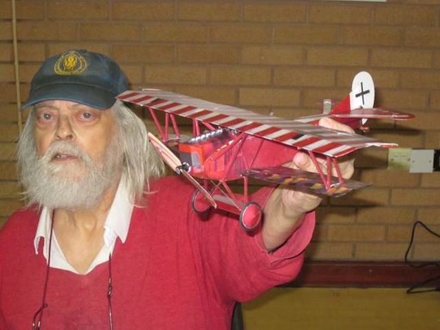
Its clear that the designer(s) has gone to great langths to create a kit which doesn't need any painting. The problem here is that any mismatch will produce a very noticeable piece of white depron. From my own point of view, I detest unpainted edges of foam models and it was inevitable that I would have to paint those anyway.


A little paint works wonders
The fuselage structure is quite challenging. There is a keel made from 2mm depron and a 1mm depron skin which is bent around it. The keel is very flexible which makes it difficult to bend the skin around it. The top decking in front and behind the cockpit has to be curved around the formers. To aid this, the inside of the decking has to be scored to a supplied diagram. I found that this didn't really help a great deal. I doubled up on the scoring by adding score lines between those indicated and then rolled the decking around a small diameter tube. I then forced the decking around the formers with the aid of 'UHU Por' but still ended up with steps rather than a curve. If I were doing this again, I would probably try to bend the decking around a heated tube. Despite all my efforts, I ended up with a slight offset on the nose. OK, banana-shaped fuselages are not uncommon! During this operation, I tried using 'foam friendly' CA glue. It doesn't work at all well unless you use an activator. Not only is this messy, but I am allergic to the stuff.
Certain parts of that 1mm skin nave to be bevelled on the edges. I wonder how many people can bevel the edge of 1mm material and tell the difference between 45 and 30 degrees? This eighty year old (with corrected eyesight) found it great fun! That's one to the traditional modeller!
The fuselage rear decking really is a challenge. The problem here is that 1mm depron (unlike thicker depron) has a hard skin on each side which makes it difficult to bend or curve. The decking is too long (in the beta kits). I assumed that the decking would butt up against the tailplane, but have since discovered that it is meant to overlap. Having trimmed some from the rear to butt against the tail, I also had to cut pieces from the front to meet the front decking. There is no support for the sides between the formers at the front and rear of the decking. I cut pieces of spare depron to space the sides out to match the fuselage bottom. The centre of the decking appeared to be too wide also. If you are following the recommended assembly sequence, you glue the fuselage bottom on first and it is difficult to attach the decking to the sides because you have no access from below.
The lower wing is made up on a dihedral jig and then attached to the fuselage. The fuselage bottom from the trailing edge to the nose is then added. This has tabs which have to be folded up to fit the shape of the lower wing. Here I profitted from experience and cut the tabs away from the bottom, bevelled the edges and glued them back on. The front of the fuselage bottom has to be bent in two places to make an octagonal shape which matches the nose. It is worth pointing out here that the real aircraft has a gentle three-dimensional curve into the propeller.
I must admit that I had my doubts about the undercarriage, which is basically made from polypropylene with carbon reinforcement. In fact, it works well and will take a surprising amount of punishment. Both wheels are glued to the axle and cannot rotate individually. On my model, this made it difficult to steer on the ground and prone to groundloop.
At this point, I went ahead and made up and fitted the top wing. This was a mistake and I would reccommend that this is left until dead last. It will be easier to fit the radio and motor and make up the rest of the nose, if it is out of the way.
The original instructione suggested that the radio should be sited as far back as possible. My model required 4 gram of nose weight so I would suggest as far forward as possible. I ran into an unexpected problem here, because the reccommended radio was too wide to fit in the fuselage. There are narrower radios available, but my cure was to fit the radio at an angle. This leaves the receiver too high, so I cut away one side of the tray (D4) so that it would fit lower. I also must admit that I didn't like the thin wire pushrods to the tail surfaces. I would have preferred carbon. I did try this but the formers got in the way, so I decided that I had to try things as intended, otherwise my feedback wouldn't be much use. See later.
The motor/gearbox is fitted to a ply plate, which is the glued in the nose. The gearbox is actually fitted inverted with the propeller shaft at the bottom. I was unsure whether the mounting lugs should go above or below the plate. The videos of the prototypes flying showed a tendency to porpoise, which indicated to me that some downthrust was required. In my case this meant that the lugs must go above the plate, otherwise the propshaft would be too low. The battery is mounted above the motor and a mounting plate is supplied for use with the usual velcro attachment. Velcro simply doesn't work for me and I made up a new tray from plastikard and depron with my usual rubber band retainer.
The upper nose forms a cover for the gearbox and battery. Here again, you have to form 1 mm depron into a curve. I started by actually folding the material along the top of the sides and then scoring between those points. The polypropylene liner merely requires folding as above and will curve quite well without scoring. This assembly is held in place by magnets and this works well.
I ran into all sorts of problems with the top wing, largely of my own making. I started by attaching the interplane struts to the bottom wing. Next I attached the cabane struts to the top wing. I then attached the cabane struts to the fuselage. This was quite difficult, because the wing got in the way. The way the model is designed, all of these fittings fit in place using tabs in slots. Despite this there is some variation possible because of the material used. In my case, the shorter of the cabane struts appeared to be about 1 mm too short and I had to stretch things a little to make it fit (Moral: never MAKE things fit). Finally I glued the interplane struts to the upper wing.
All my initial flying attempts were made at a local indoor meeting (not at all ideal), with an audience. There was ageneral consensus that the model needed dihedral. They weren't flying it - that was the least of my problems. Flying did not go at all well. The postmortem revealed that while the right wings were nice and straight, the left wings both had pronounced washout. I cut away the interplane struts on the left wing and tried to remedy things. I really thought I had fixed it, but it didn't fly any better. Investigation revealed that the warp was back. I tried offsetting the ailerons, but that didn't really work. I tried jigging the model up on a worksurface so I could make some real measurements.
At last, it became clear. The top and bottom wings were not parallel (so much for my making things fit) which was producing the warp. I cut all the cabane struts away from the fuselage (and the left interplane strut from the top wing) and, after fixing the wings parallel to each other, glued the struts back to the fuselage one by one, checking after each. Finally I glued the left interplane strut back to the upper wing. At last, I had a straight aeroplane!
That should have fixed it but it was still difficult to fly. I was getting paranoid by this time until I found that there was a lot of lost movement in the elevator, I cut the bottom the fuselage open (needs must) and found that the flexible wire pushrod, which had to bend around the formers, was changing its shape when pushed and pulled and never returned to straight. I cut away as much of the formers as I could reach and reduced (but not eliminated) the effect. A cure will mean almost total reconstruction of the fuselage. Interestingly, previous Microaces kits have used this flexible wire pushrod, but run in a tube.
At last a calm morning appeared (5am and cold). I was able to make two long flights on the local recreation ground (3:39 and 5:09) which revealed that all was now fine apart from that lost movement in the elevator. I managed to trim the model so that application of 'down' would give the correct trim. Any application of 'up' had to be followed by 'down', but it worked!
Maybe the model is doomed anyway. Early on in the flying stage, the gearbox seized. I had to cut apart the nose of the long suffering model to fix it. The cause was that the propshaft had seized in its bearings. There was some kind of coating on the shaft which I had to scrape off. I've never seen this before. I normally take a new gearbox apart and grease the shaft with silicon grease. I didn't do that in this case (the gearbox came out of another model which had been well flown).
One thing that is really impressive about the finished model is the amount of punishment that it will take. I had my doubts about the polypropylene undercarriage, but it works beautifully. The model has been crashed umpteen times and has now been cut apart four times, but you would never know. It is advisable after every 'arrival' to check that all the cabane struts are still attached to the fuselage. Do the same if you experience any unusual flight characteristics.
The purpose of the beta kit appears to have been acheived, because the final kit has many modifications aimed at addressing the various issues raised by beta kit builders and subsequent kit introductions are going through the same process. The instructions have been rewritten to incorporate all the changes.
Thank you Microaces,
The touching up of various bits of paintwork was done with Humbrol Acrylic paint #60 (Matt Scarlet) with a touch of #33 (Matt Black) added.
Other details:
Rudder throw: 90%
Elevator throw: 60%
Flying weight: 40.6 gm

